Every once in a while I’ll see a tool/project that calls to me. You know, one of those “whatchamacallits” that real people probably don’t really need, but looks so cool? As you might imagine, the majority of THOSE projects never see the light of day in my shop. Luckily, there are also some other projects that REALLY, REALLY, call to me, and just happen to be both cool and useful. This article is about one of these latter types of projects.
Christopher Schwarz, who is a friend of mine, and someone almost everyone in the woodworking community knows, teaches how to make a really cool wooden square. After seeing his, I just had to give it a try. While Chris’ pattern is straight from an old original square (which I believe was inadvertently destroyed when in transit by a package handling company), I created my pattern simply by eye-balling the square Chris showed on Roy Underhill’s “The Woodwright’s Shop”, and extrapolating what dimensions looked right to me.

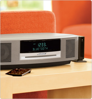
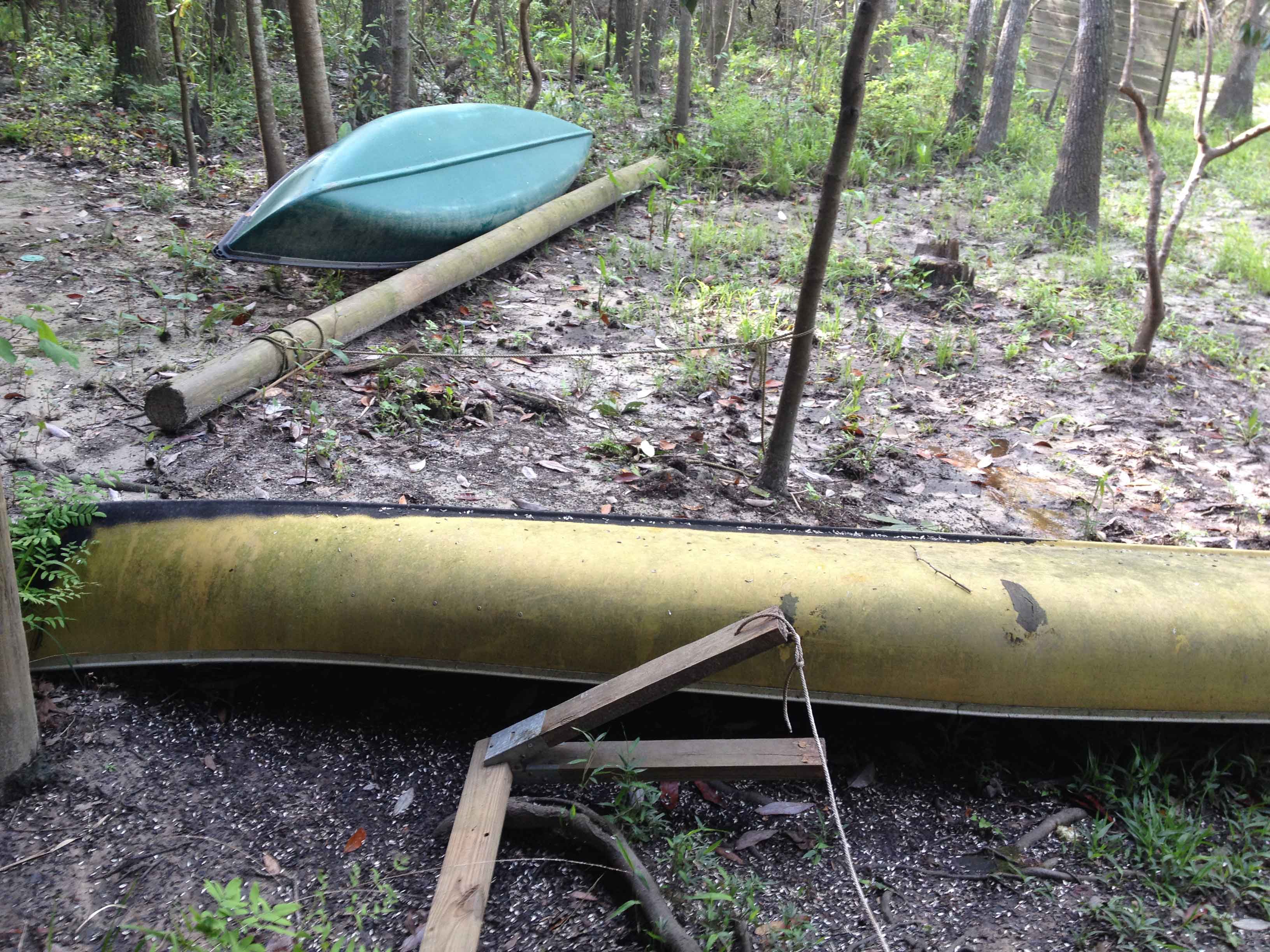
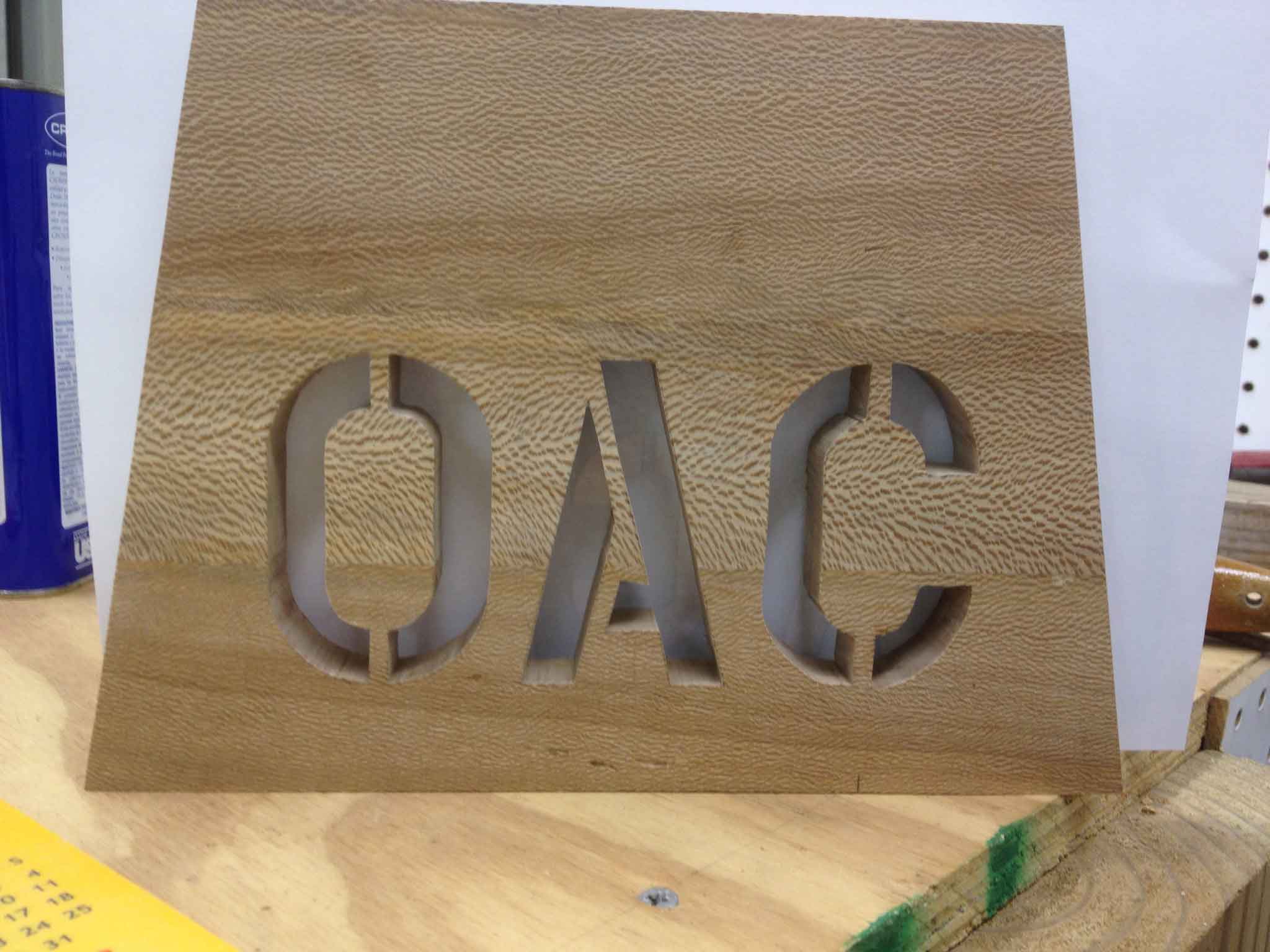
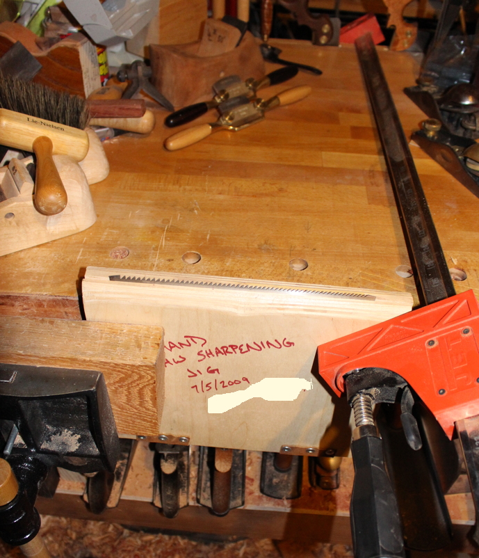
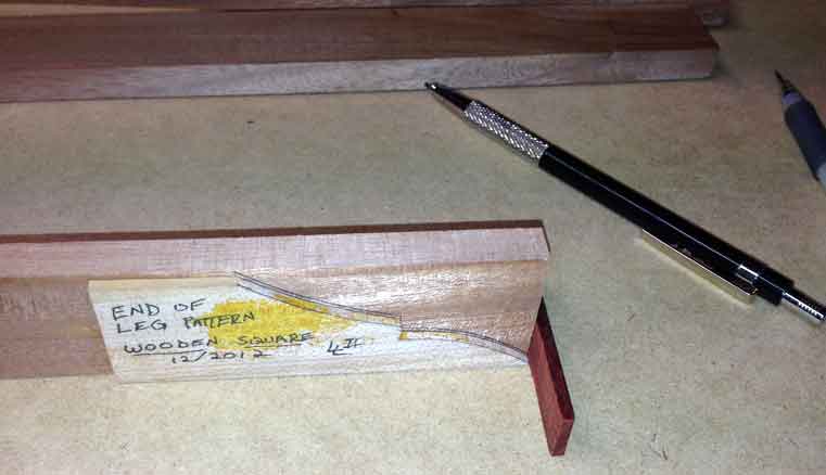
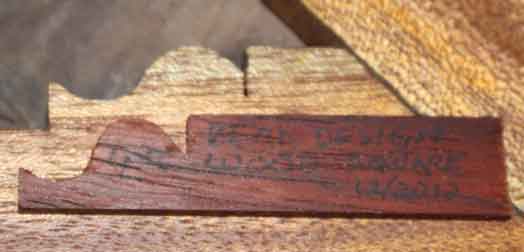
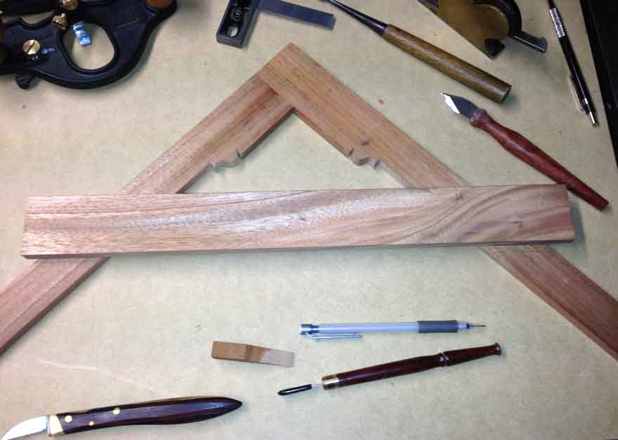
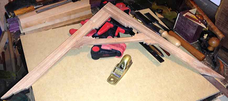
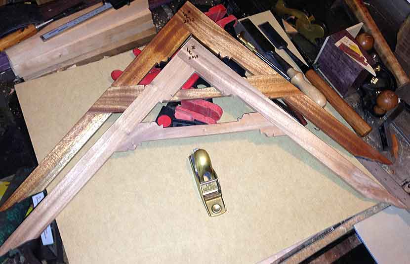
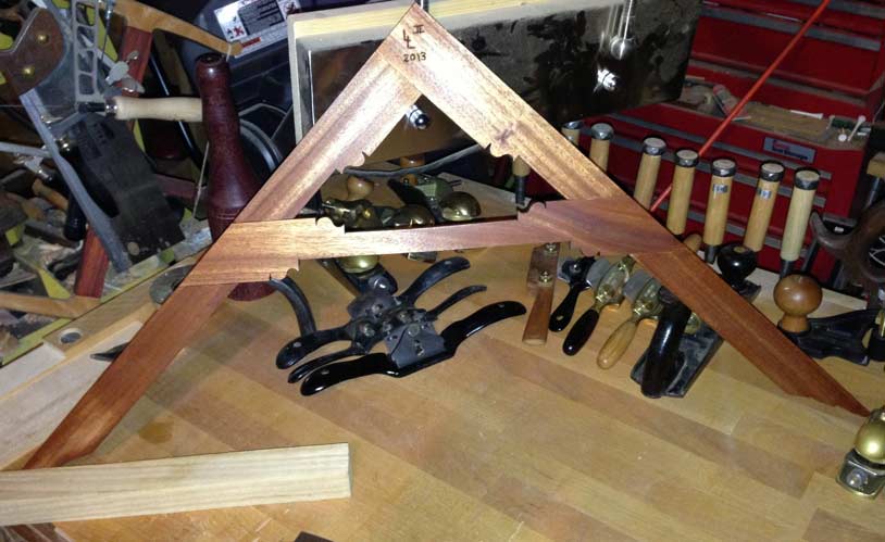
A quick photo of my square in front of some of my tools.
After seeing that the square is made from only three pieces of wood, I figured I’d go spend an hour or two in the shop and have a square. Well, I’d have to say my time estimation and management skills must have been very lacking that week. Ok, it didn’t actually take me a week to make the first one, but the time was certainly adding up. And this was with me already having the necessary wood milled up to 1/2” thick, which I’d originally planned to use on a dovetailed box project. The box will just have to wait!
To start out, I cut two legs 22” long x 2” wide x 1/2” thick, and one cross-member 20” long x 2” wide x 1/2 thick. Before cutting any of the decorative shaping, I hand planed each board, making sure they were both square and flat. Much of the next work is focused on the two “leg” boards, since its only after they are glued into a solid unit, that you can identify exactly where the cross-member will intersect the legs. If you try marking the locations to evacuate for the cross-member, without first gluing the legs, I’d suggest your chances of success would be diminished.
Before marking either of the two “leg” boards, you’ll want to examine them for any imperfections and read through the meat of the project, as it’s possible you just might be able to plan for any problem areas to fall in the region that will be removed as waste. Since the square’s design uses a half-lap joint where the two legs intersect, there is a fair amount of wood removed, which you can also view as an opportunity. If either of your leg boards have any tear-out or other quality type issues in the first 2” of the board, you can orient them so the problem section will reside on the slab of wood you remove when forming the joint. But, before finalizing any cuts or using any cutting tool to mark, I find it’s a good idea to lightly sketch out the complete layout, so you can weigh your options on which areas of wood might create the least amount of extra work. At the minimum, this will at least give you the chance to choose the best orientation for each board. It may just be that the half-lap joint area is of less concern than another area. If you’re really into planning, or end up being lucky, you may also find a similar benefit when positioning the cross-member, but there are only a few ways to orient three boards. You’d may as well take every advantage to eliminate blemishes on your project, especially when it only takes a few moments to flip the boards around, testing for the best orientation.
Now that you’ve looked everything over, its time to get on with the design, which obviously includes the areas you’ll cut away as well as the design features on the legs. To start, I measure down approximately 6 inches from the end of the board that will contain the half-lap joint and place a pencil mark across the board, on what will be the inside edge. This top section of the board will stay full width and includes both the half-lap joint as well as some figurative work before the leg narrows. Measure in 5/8” from the location you just marked, and using a square, run a line to the other end of your leg board away from the half-lap end. This line should be parallel to the edge of your board.
Repeat this process on your other leg board, as the design is identical on both legs.
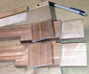
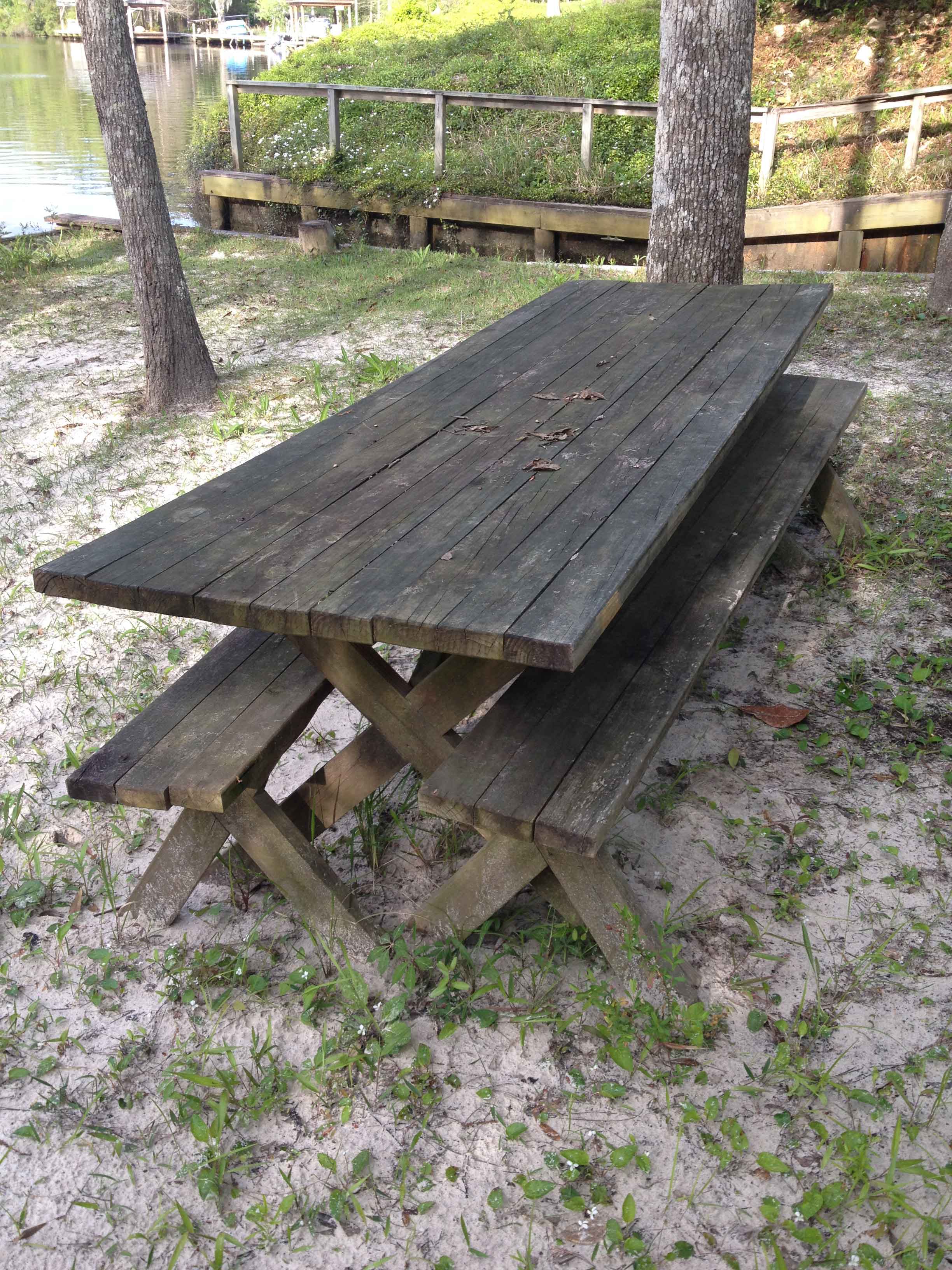
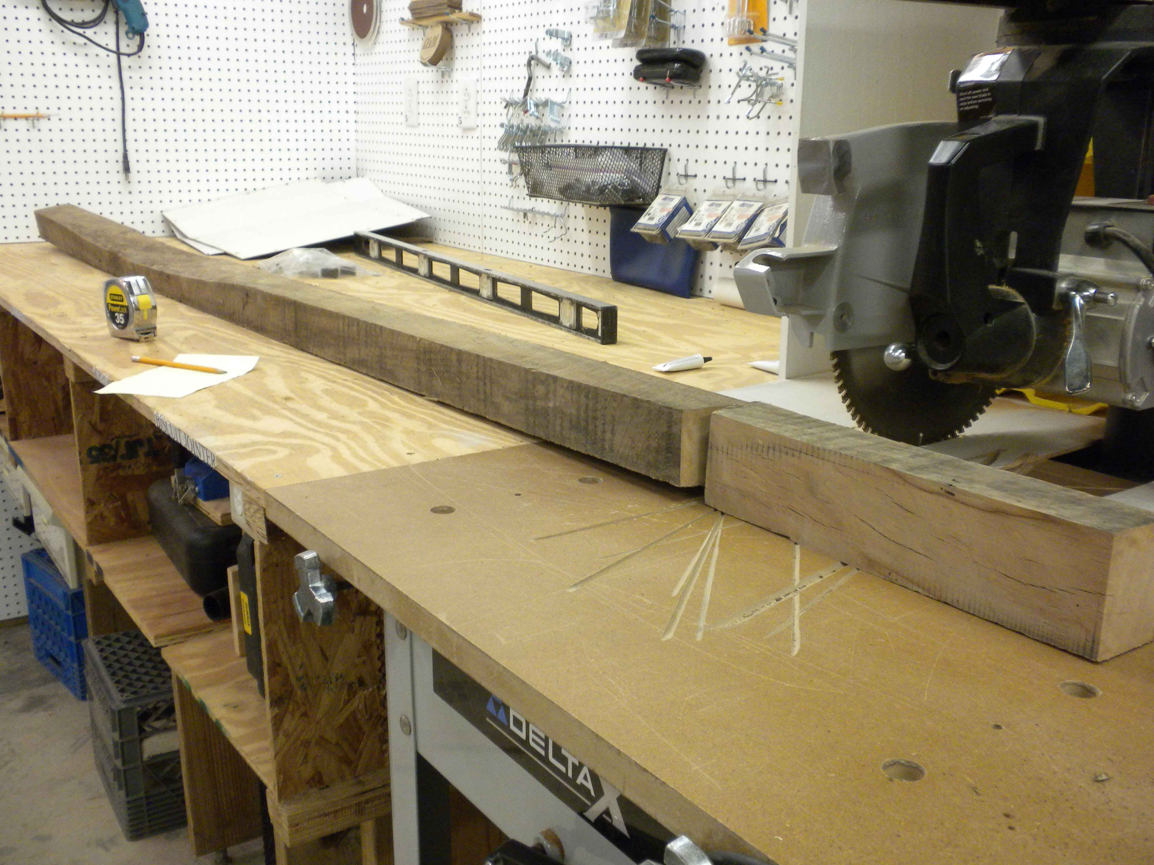
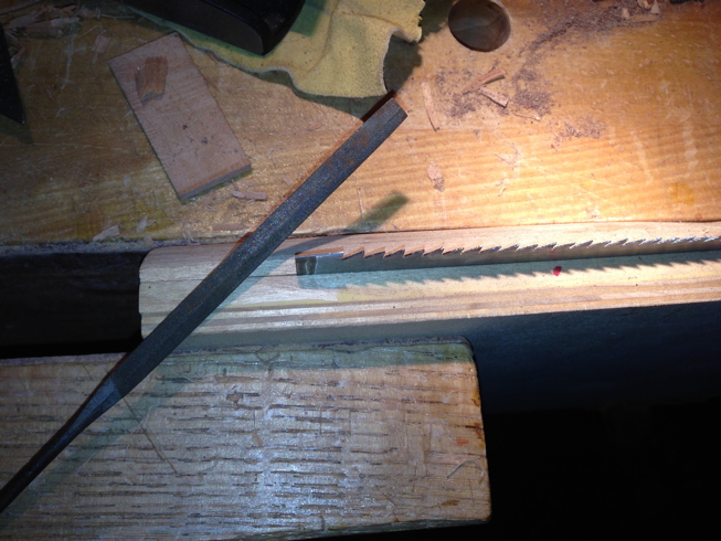
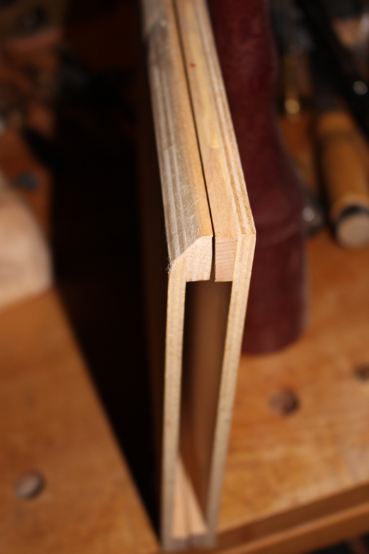
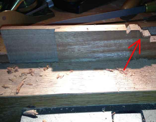
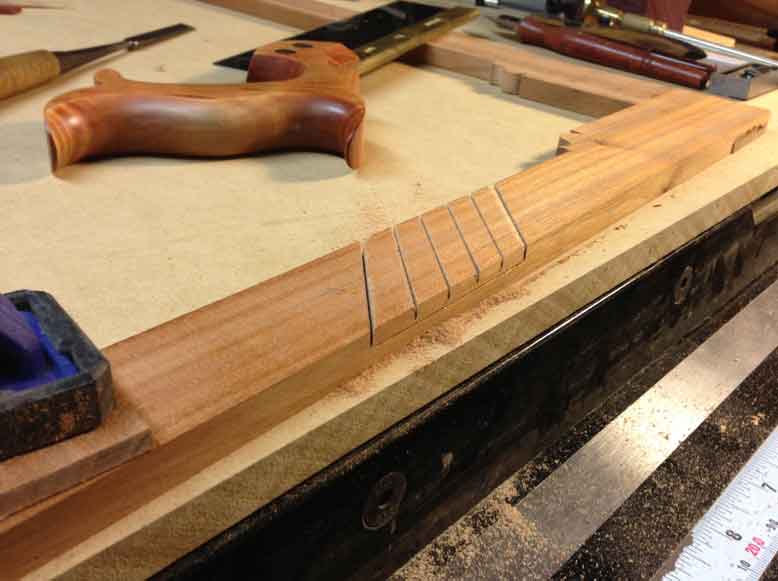
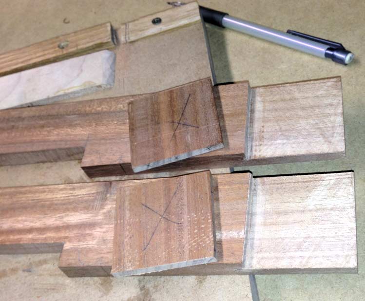
It is approximately 6 inches from the end to the notch just left of the off-cuts, which is from the 5/8” cut. You can also see the large X on the slabs which identified the waste, and the saw marks still on the lap joints before using the router plane.
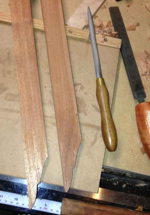
Cut the short 5/8” deep cut from the inside edge of the board first, followed by the long cut from the end farthest away from the intended half-lap joints. Making the short cut first is much easier than trying to back out of a long cut. Use whatever saw you have available that can reach this far into the wood, like a band saw, a bow saw or a panel saw. This cut will generate a 5/8” wide piece of wood that is approximately 16” long. (anyone up for making a kite?)
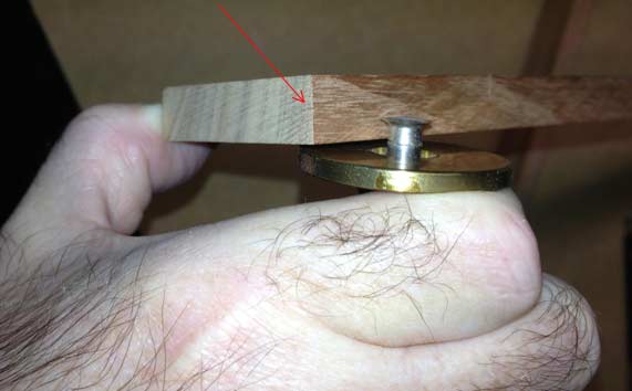
The next step is to mark out for the half-lap joint for the legs. Set your marking gauge directly from the width of the first board, and add a hairs width extra. With the gauge head riding against the end of the second board, lightly mark across the width of the board, which transfers the first board’s dimensions. Make a couple of additional passes, applying a little more pressure on the marking gauge on each pass.Before moving on, take your pencil and make an “X” on the leg above the mark you just made. This will remind you that this is the side from which the wood is removed, which can help prevent errors. Repeat the process for the other board, but remember to set the gauge from the opposite board’s width, just in case they aren’t exactly the same size. Next you’ll mark the center line of the board’s thickness on the end and the sides of the board, down to the line you’ve just marked across one face. I dial in my marking gauge directly from the thickness of the board, by lightly touching the cutting gauge to the board while the head is against one side, and then doing the same from the other side. When the gauge hits the same spot from both sides, you’re there. I still like to add an extra hair’s width, so there is a little extra material to dial in the perfect joint, which I’ll talk about later.
While holding the gauge’s head against the side of your leg that will remain (the side without the big “X”), mark across the end and down both sides, to your line across the leg. If you accidentally reverse the gauge, so the head is against the side you plan to remove, you’ll end up with a joint that’s isn’t as thick as the original leg.
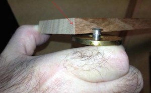
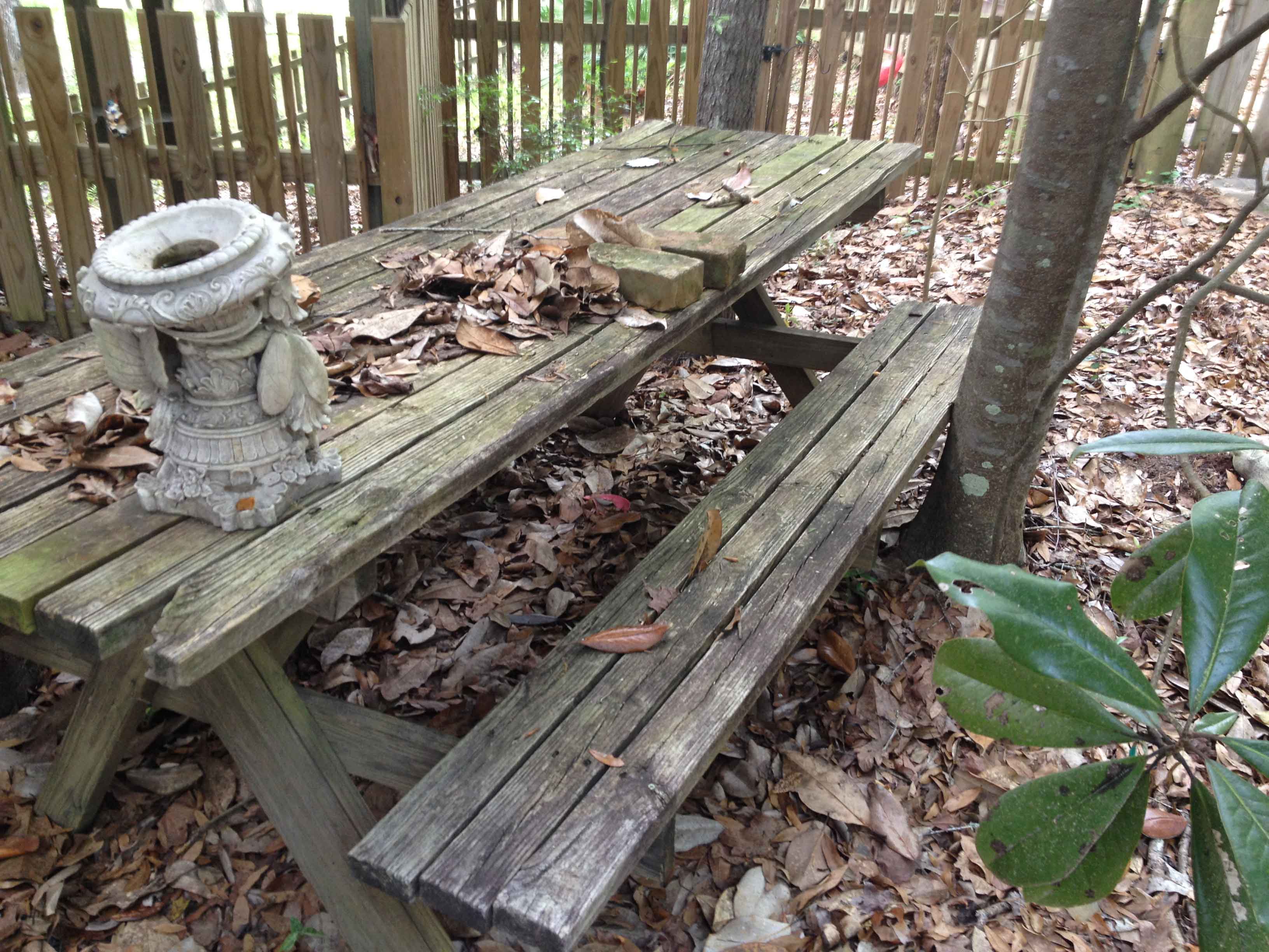
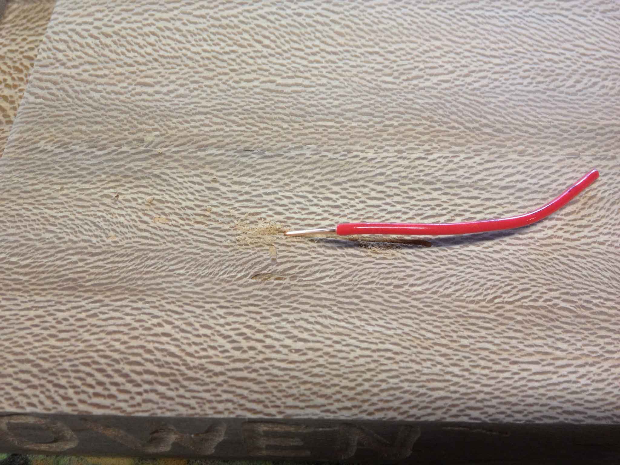
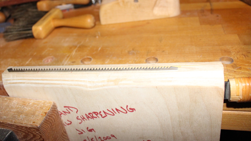
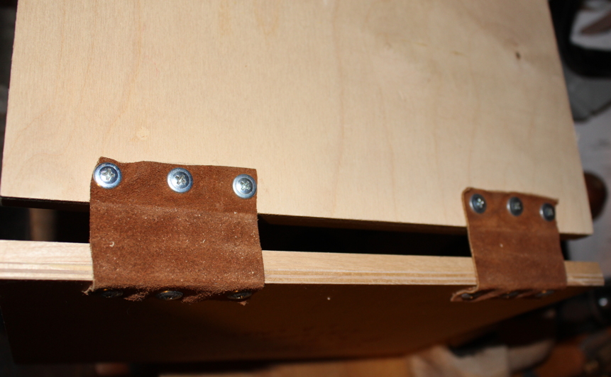
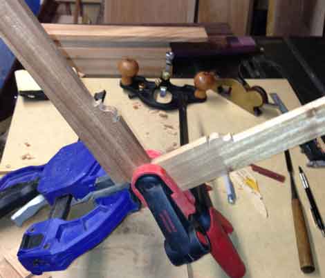
Showing gauge out to depth and red arrow points to centering mark from each side.
Now that your leg’s half-lap joint is marked, it’s time to remove the excess wood. The first cut is at your mark across the leg, but I like to give myself the best chance to succeed. Instead of just grabbing my crosscut saw and going for it, I use a razor sharp chisel to carefully pare away a small angled piece of wood, across the width of the board. I do this on the waste side of the marking gauge’s line, to create a small V-shaped path, which helps keep the saw from wandering during the initial strokes. Now use a crosscut saw to carefully saw down, until you just about kiss your gauge lines on both sides, which is very close to half way through the board.
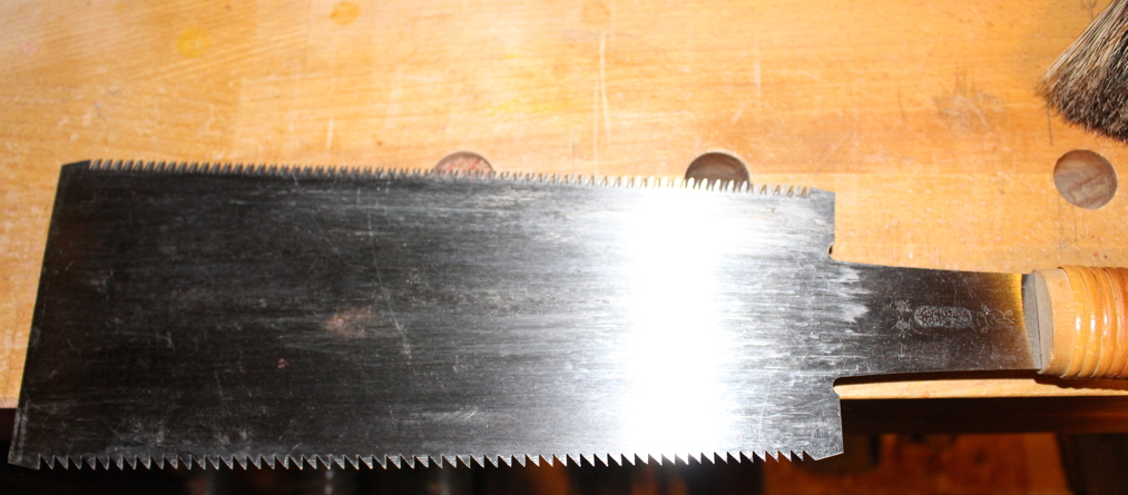
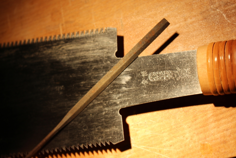
The next operation is to saw down length-wise following the marks made on the sides and end. Since this cut is with the grain, use a fine-toothed rip saw, of which I prefer to use a thin-bladed dovetail saw. Place the first leg board into a vise with it tilted so the top end of the board is just slightly away from you.
This is another good place to apply a helpful tip, which is to remove a small wedge shaped piece of wood at the corner of the board closest to you. With a sharp chisel, place it so the flat back lines up with the mark you’ve made across the end of the board, push the chisel into the wood so it is contacting the corner. Turn the chisel around so it’s back is away from the line and at about a 45-degree angle, push in again, so the two cuts meet. This should pop out a small wedge of wood that will act similar to the cross-cut version earlier, but the starting “V” is not all the way across the end. Start with the toe of the saw raised up slightly, so it is not making contact across the full width of the board’s end. With light, short strokes, let it gradually drop, as you look to make sure you follow your mark. When the saw is down to the point where it is touching across the full width, focus on following the line on the side of the board closest to you, cutting down to the baseline. This ends up being an almost purely diagonal cut, since you are only trying to advance the saw plate on the side you can observe.
Next, remove the board from the vise and flip it around so you have the other side of the board facing you. Again tilt the board so the end is slightly leaning away from you, and again make the same diagonal type cut down to the baseline on this side. Next, it is just a matter of placing the saw into the already created kerf, and while holding the saw so the teeth are parallel to the baseline, cut down through the remaining triangle-shaped section of wood. Be very careful at this stage, especially when you’re getting close, that you don’t cut down below the baseline, which can happen if the saw tilts forward. Since you can’t see the opposite side of the cut, without moving your head around, this is the most common place to over-cut. This will leave you with your basic half-lap shaped end on your leg board.
Repeat these steps on the other leg board. When I make these cuts, I saw so I am cutting really close to the line, but making sure I don’t dip down into it by accident. You can base how close you cut to your lines, on your comfort level with a saw, but remember I’ll share additional techniques that will help create a perfect fit.
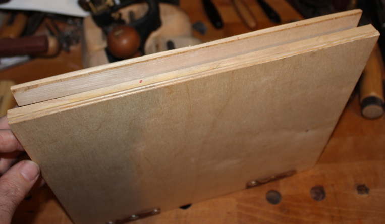
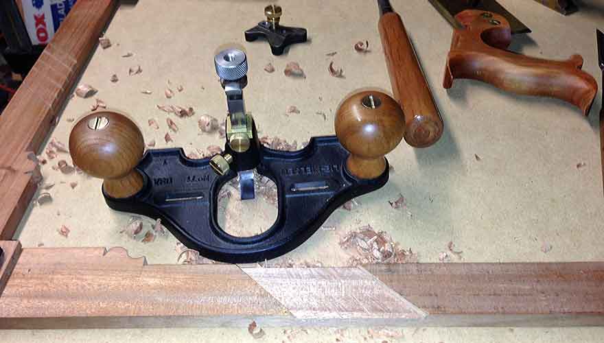
Next, we’ll get out the router plane, which is a perfect companion for the upcoming tweaks to the wide mating surfaces of the lap joint. Clamp a leg board so it is sitting with the half-lap portion facing upwards from the bench. Place the other leg on one side of the first leg, and the cross member on the other side of it, so the router plane can ride on two rails of the same thickness. With the router plane on the two flanking boards, lower its iron down until it just grazes the highest point on the lap joint. (It’s also a good idea to check to make sure the iron isn’t below the line that was earlier marked down the side of the leg board, as that could be close to removing too much material.) Move the router plane back and forth so it’s iron travels over all areas of the half-lap, while riding on the two side boards. Gradually advance the iron so a very light shaving is taken from all areas of the joint. Before removing any material below the lines you marked earlier, do the same process to the other leg’s half-lap. Test the two pieces together, to see if the joint is still thicker than either leg, which would indicate additional material is still remaining. Continue to remove very light shavings equally from each surface until the full joint is exactly the same thickness, when compared to the original thickness of either leg.
The last half-lap related assessment for this joint is of the earlier-cut shoulders, across the legs. Check to see if the shoulder is both square across the board and square to the inside faces. If either of these are out of square, they will prevent the two boards from mating properly, with gaps and/or legs that are not 90-degrees from one another. If there are obvious gross adjustments needed, you can use a sharp chisel (or a rasp) to get it close to the proper alignment, but I’d hesitate to use that tool for the final adjustment. The shoulder plane is my tool of choice for this work, as its wide sides register against the earlier flattened faces, creating perfect 90-degree shoulders. Set the shoulder plane for a very fine shaving, and make sure to keep the side of the plane against the reference surface. Also, check to see if there is any grain runout in either direction, as the shoulder plane works equally well on either of its sides. It only requires you to set the iron so its outside edge is in line with the plane’s body. If you cut the earlier shoulders just proud of your marking lines, you can easily bring the excess material down to the line, knowing you’ve reached the stopping point. If you didn’t leave your line, you could always re-mark down about 1/64” (remember to do this on both legs, and reference from the joint end of the board, just so everything stays symmetrical), so you don’t have to guess where to stop. This isn’t super critical for this tool, as long as the shoulder is square in both discussed dimensions, no one will notice if you don’t tell.
Now, before you get excited and decide to glue your perfectly fitting half-lap joint together, remember we still have some more work to do and it is much easier to accomplish while the legs are still separate from each other. We’ll get to this in Part 2, so stay tuned with our Wooden Square Build!
CLICK HERE to go to Part 2 of the Wooden Square Build.
Lee Laird has enjoyed woodworking for over 20 years. He is retired from the U.S.P.S. and works for Lie-Nielsen Toolworks as a show staff member, demonstrating tools and training customers. You can email him at lee@lie-nielsen.com or follow him on Twitter at twitter.com/is9582