Highland Staff

Nov 262013
 

Ok, so do you have a card scraper sitting around in your shop collecting dust? If you do, don’t think you’re alone. I’ve talked to a large number of woodworkers across the country that are in a similar boat. I’ll provide you with some easy to follow instructions that will hopefully make the card scraper one of your go-to tools from this day forward. Oh, one caveat… The quality of steel in your scraper can absolutely make or break this success. I know first hand, as I had a card scraper in my shop early on, and no matter what I tried I just couldn’t get it to work properly, or if it did, it would only last a few strokes. I finally decided on a whim that I’d buy another card scraper, just to see if it was me or the scraper. Well, I’m sure glad I did, because the second one worked like a charm. I’ve even gone back to the original one (yep, I still have it for times when I want to dig in and do something I wouldn’t really want to do with my good scraper) and applied the same techniques, but to no avail.

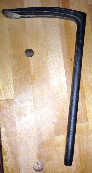
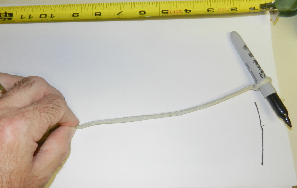
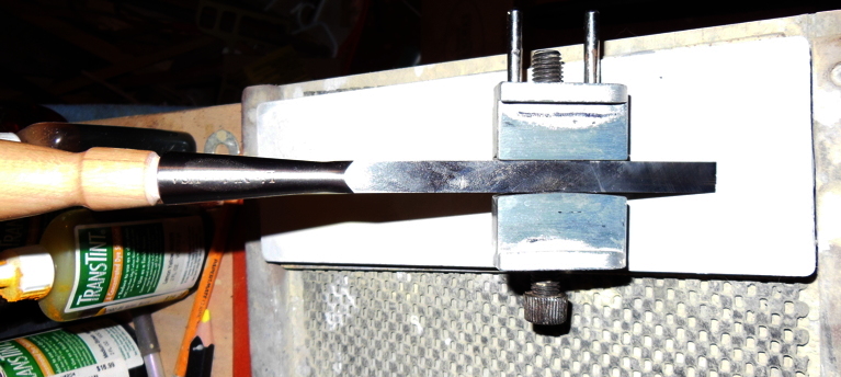
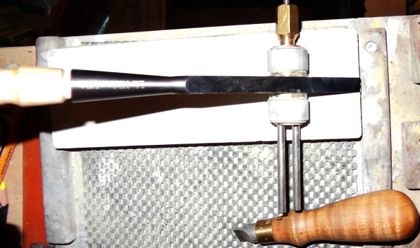
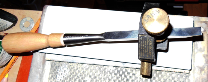
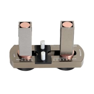
When you first get a card scraper, the likelihood is that its edges will be similar to when you buy a new handplane. Not too bad, but certainly not to the level where you get your best results. The first thing to do is to file the two long edges of the scraper. I use a scraper file/burnisher made by Glen-Drake, which provides great results and helps make it easy to accomplish. Before getting started, I made a spacer block the same thickness as the distance from the file surface to the outside edge of the handle (see photo below). Make sure you test your spacer by placing the file on it, while the handle is on the bench. I put a light source behind the block and made sure no light was leaking through towards the handle or the end.

cardscraperblog1

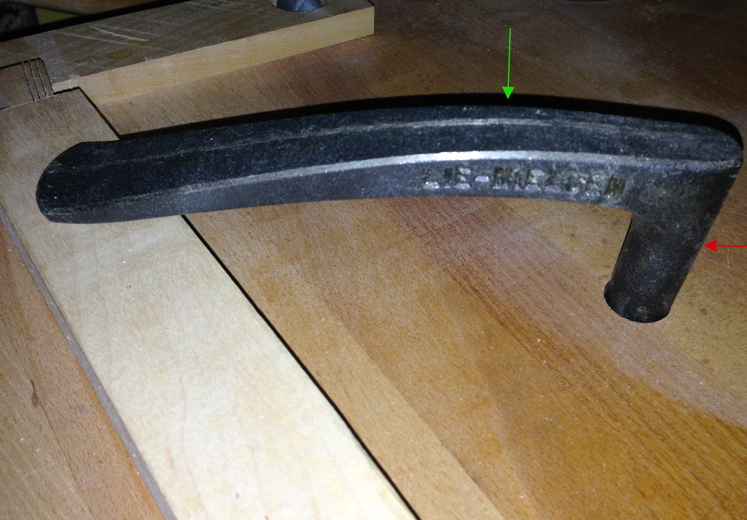
In the photo above, I have the handle of my file resting on the workbench surface and the file clamped in my bench vise. When clamping, I hold the scraper against the spacer so it is the same height above the bench. With the scraper at this height, it’s simple to keep a flat and square surface on the scraper edges. All you have to do is keep the handle of the file on the bench while moving it down the scraper surface with light pressure. One little trick I use is to coat the edge with black Sharpie so I can tell if my file is taking material equally across the edge of the scraper. One other thing I do is hold the file in a similar position to that in the photo, rather than trying to move it down the scraper from the tip of the file to the handle. The way I hold the file tends to have less chatter on the scraper, so less junk to remove later.

cardscraperblog2

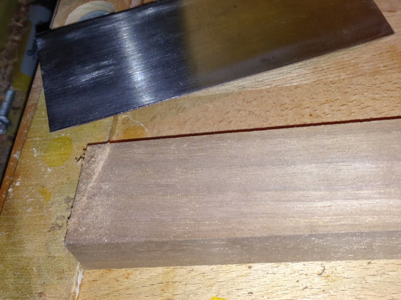
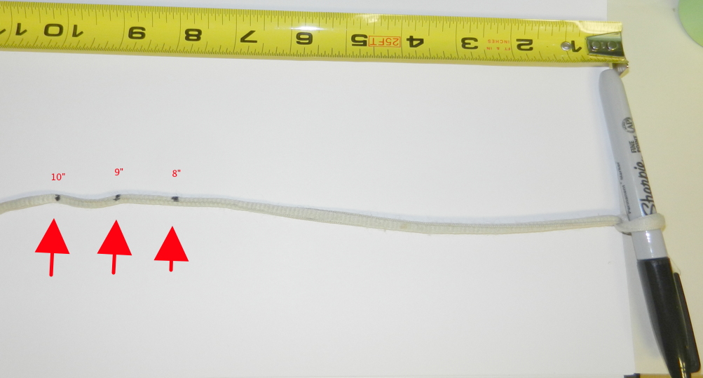
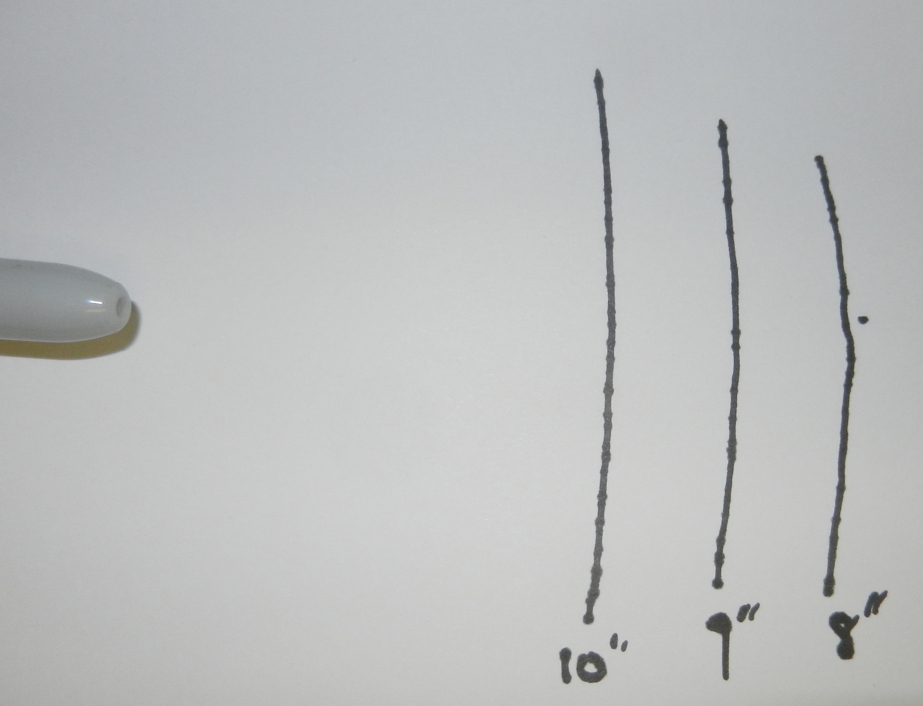
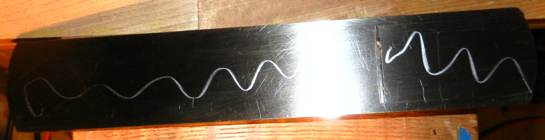
Above is a photo of the scraper’s results if used immediately after filing the edge. As you can see, it’s mostly dust, but there are little “almost” shavings. I thought it would be nice to have the comparison between this stage and the final surface.

The next step is to knock down any burr that either previously existed, or is now there from the filing. Depending on the type of stones you have, softer being a bigger deal, I sometimes use the same file with a pass or two to remove the burr. This is simple and quick. Another option is to use a diamond plate or even a hard 1000-grit stone (like the Shapton Glass series). After you have eliminated or at least reduced the burr, it’s time to hit the stones. Place a thin ruler on one edge of the stone so that side of the scraper is lifted ever so slightly, placing your efforts at the opposite edge. This focuses the work where needed, rather than basically working the whole surface of the scraper. Work on your 1000-grit stone first and then move up to 8000-grit or 10000-grit. The end result should be a very narrow polished band at the edge (hard to capture with a camera), on all four long sides of the scraper.

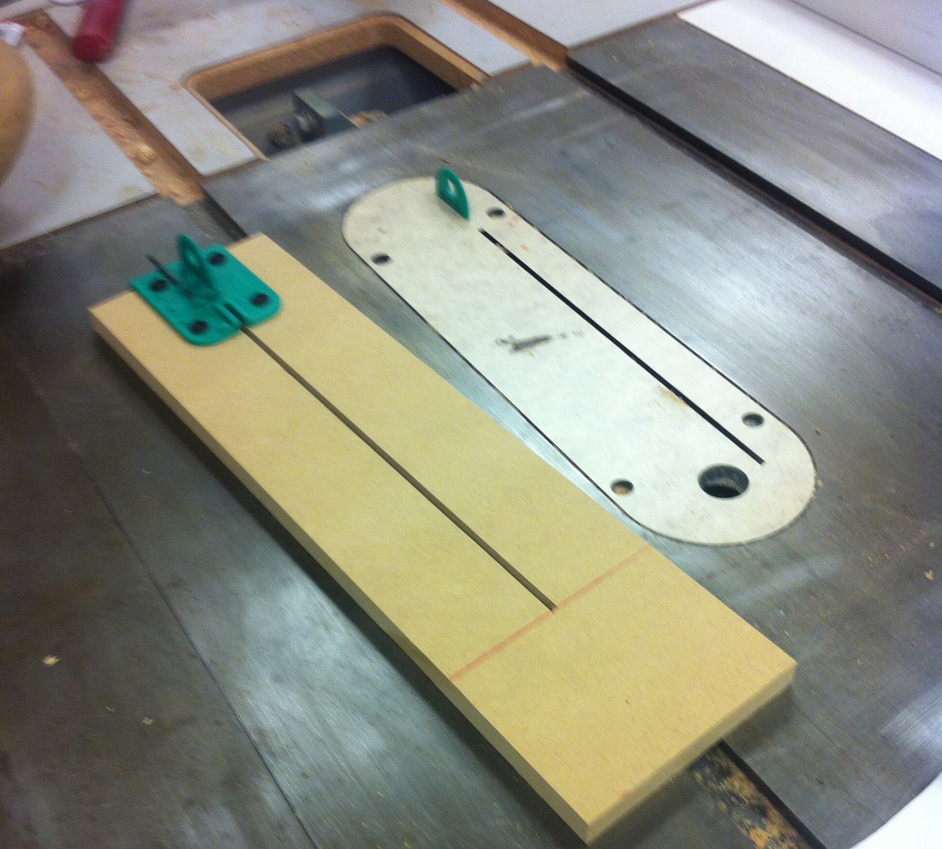
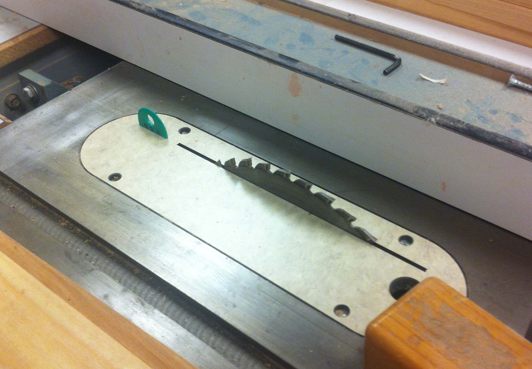
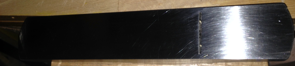
Next, make a wooden block (unless you have a piece of high density plastic, which I like better) that is almost as tall as the scraper is wide, and make certain the edge of the block you use is square to the bottom surface. This is to support the scraper on the stones when up on edge. Again, use the same 1000-grit/8000-grit stones, but make sure the scraper is oriented as if you were drawing a diagonal on the stone, and push as if moving straight down the stone. With the scraper angled to the movement it helps prevent creating a groove in your stones. If the scraper was oriented straight up and down the stone, the grooves would occur readily and by the time you finished, would be substantial. As usual, work each grit until the scraper has a consistent surface (a dull grey on the 1000-grit and a polished surface from the 8000-grit).

Now you’ve finished the prep work, so it’s on to creating the cutting edge. Well, that’s really not exactly true. The cutting edge is already there and you can test this if you’d like. It’s not as aggressive as it will be after the next step, but it will take a shaving. Just remember that the angle at which you engage the wood is different.

Lay the scraper flat on your bench, along the edge, and carefully move your burnisher up and down the wide surface at the edge. If you don’t have a burnisher, a carbide router shank will work, but be careful you don’t accidentally cut yourself on the router bit. This is done on all four edges. **Since I’ve been using the ruler trick on my stones, I’ve omitted this stage and the scraper behaved equally as well.

Clamp the scraper again in the bench vise and get your burnisher.  I usually run the burnisher down the edge, holding it level with very light pressure. I then drop the handle side down ever so slightly and again lightly run it down the edge. I stop when I’m probably around 5 degrees, and it’s surprising at just how little pressure is required on these passes. If you’ve never tried it like this before, give it a shot with just the amount of hand pressure you might apply when shaving. Very light, as you don’t want to dig into your face/leg (men/ladies).

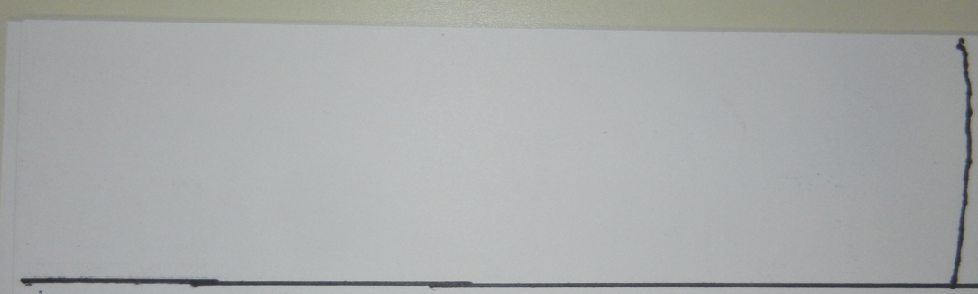
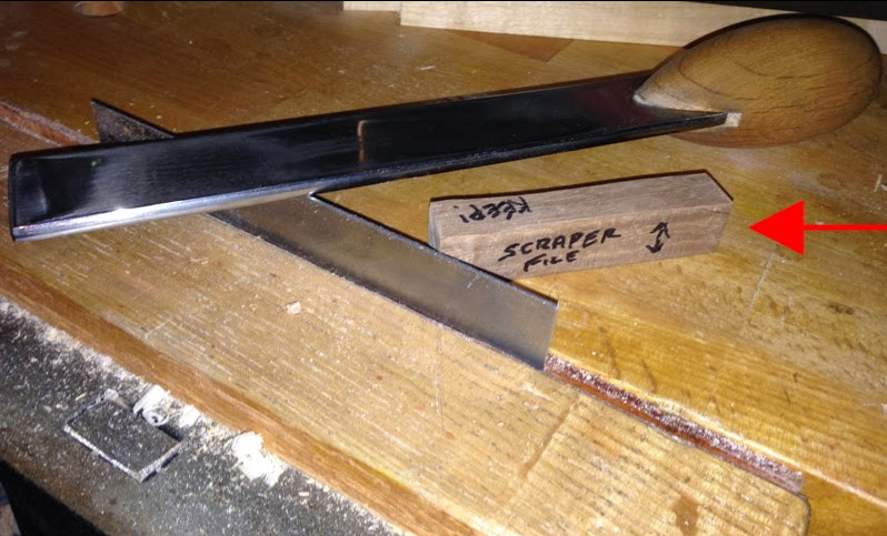
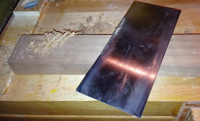
Below is a photo of the same piece of Walnut as in the second photo, which shows the shavings the card scraper produced after going through the full sharpening/burnishing techniques. Decent results after just a little bit of work!

cardscraperblog3

It is also very surprising at just how a little burr does a better job and will last longer than if you create a large burr. Part of that is probably obvious when you think about it, as a thin piece of metal sticking further out is more likely to bend with similar forces.

I hope this helps anyone that has had trouble in the past or for those who have never tried a card scraper before. When you get used to doing the steps it’s usually not more than about 5 minutes to be back to making shavings. If you have trouble getting a cutting edge or keeping one, it may just be the card scraper isn’t of good quality, so just upgrade to a better one and you’re off to the races.

Thanks for checking out my blog and let me know if you have any questions or comments.

Lee


Lee Laird has enjoyed woodworking for over 20 years. He is retired from the U.S.P.S. You can email him at lee@lie-nielsen.com or follow him on Twitter at twitter.com/is9582


Nov 062013
 

Well, dern!! It is obvious I cannot live without one of these Galbert Drawsharps.

I am a big fan of Peter Galbert and the man is just amazing to me both with his Windsor Chair skills, and his mechanical inventiveness.  I took his chair making class at Highland a few years ago and he is coming back next March to do another one. By the way, if you want to see my chair built in Peter’s class, look in the front window of Highland and see it sitting next to an original Dunbar and an original Maloof. Turn it over and see my signature on the bottom. Not that my skills are worthy of such august company, but hey, there it is. I plan to mention having a chair in the front window of Highland in my obituary many years from now.

Maloof on the left, Dunbar on the right, and (dare I say it) Chapman/Galbert in the center.

Maloof on the left, Dunbar on the right, and (dare I say it) Chapman/Galbert in the center.

Peter started with the Caliper, a wonderful on-the-go diameter-measuring tool for turners. He has moved into Reamers and Travishers for chair makers and now comes the Galbert Drawsharp by Benchcrafted.Drawsharp by Benchcrafted

Sharpening is one of the great frustrations in my woodworking life. And when I take a class on chair making where I use a drawknife as a big part of the work, it is so disheartening  to see someone like Peter take a drawknife and hone it by cutting end grain on a white pine seat blank. Did you get that? He hones it not with a leather strop, but by cutting end grain on white pine. Well, now he has invented a mechanical device, which should allow me to do that too.

The Drawsharp sets the angle of the cutting edge by guiding off a couple of small pegs set in the middle of the device and running off the back edge of the knife. It is all done by hand, quiet and easy and smooth and it looks like it will work perfectly on my drawknife. Maybe now I won’t have to buy a new drawknife just because the one I have is dull.

Go watch the video on the Highland website and see how easily the Drawsharp works. If you have an old drawknife, tune it up and give it a try on a chunk of wood. Clamp the wood in the vise of your workbench and with the flat side of the blade down make a slicing angled cut. Don’t try to dig it in, just pull it towards you and take a thin shaving. Don’t jerk and snatch it along, that’s what happened to Roy Underhill’s half-brother. Just a smooth slicing cut and then come back for another. It’s like petting your cat, don’t go against the grain — always cut down hill. If you are breaking off big chunks or splitting out to the end of the wood, then you are doing it wrong. Turn the wood around. I do not consider myself a huge expert with a drawknife, but I do find myself picking it up much more often these days. It is quick and easy and will remove an amazing amount of material in a very short time. Just think what it might do when it is sharp!

DrawknifeGet yourself a Drawknife, a Drawsharp, and go to work. Shoot, take the class and make a beautiful heirloom chair by hand and people will look at it and touch it and say “how pretty” and “can I sit in it?” And you will say, “yes, please sit in it. People have been sitting in chairs just like it for 300 years and there is not a nail in it and very little glue” and “yes it will hold you up, and there are three kinds of wood to suit the places where it is used and I certainly did make it all by hand, thank you very much!” Then when you walk by it at night on the way to bed and you will touch it once more and smile.

Nov 052013
 

HF full smThe holdfast is a tool that has historically been around for a very long time, but until the late 70’s/early 80’s (if not later) it had fallen off the scope of all but the most devout hand tool woodworker. Luckily, the resurgence of hand tools has helped to bring about this wonderful version from Lie-Nielsen. The Lie-Nielsen holdfast is made out of Cast Ductile Iron which creates a very sturdy tool with enough spring to flex properly in order to either hold your project solidly or retain a batten. The latter is very useful if you are concerned about the risk of any possible compression damage to your work. Each holdfast is 13” long, has a reach of 7.25” and weighs in at 2.15 Ibs. The holdfast has a beautiful hot oil finish and a nice textured surface. The underside of the contact patch on the holdfast is ground to assure proper contact. The holdfast’s shank fits into ¾” diameter holes through your bench, and will hold securely in tops (or legs) of up to 4” thickness. If the top or leg of your bench is thicker than 4”, you may need to relieve a portion of bottom/rearward section to 1” diameter, to obtain a solid hold.

While I’m certain that many readers have seen a holdfast in use, I want to make sure I leave no one in the dark. To utilize a holdfast, the shank is placed into a ¾” diameter through-hole and a mallet or hammer is used to strike the top of the holdfast (green arrow in photo below) to seat it. I’ve used a large wooden mallet and a very small lightweight hammer and both were quite successful seating the holdfast. I have a small flap of leather I glued onto the striking face of my small hammer, so I don’t ding my holdfast, but that’s really just a personal thing. To determine if the holdfast is actually holding securely, just grab it by the head and see if you can move it. If the holdfast doesn’t move, it’s performing properly and nothing more is required until you want/need to move it or remove it.  To loosen the holdfast you strike the end of the head (red arrow in photo below), from the shank side, with your hammer/mallet swinging parallel to the bench. It can take a few strikes to loosen it, so don’t worry if the first hit doesn’t loosen the holdfast. Their ability to handle some jostling, and to retain their grip, is why they work so well in woodworking.

HF close working sm

While there have been a number of holdfast designs over the ages, Lie-Nielsen’s design seems to make the most sense to me. I’ve used other holdfasts that either had a large arc in it’s shape and/or the front section was very pointed in shape. Lie-Nielsen’s has a very low profile on the bench and the front end is fairly blunt. This may not seem as if it would make any real difference, but when you are working on your project, you might be surprised how your hands or parts of planes/tools want the same space as some holdfasts. The somewhat pointed ends on some holdfasts can certainly remind us of sloppy technique or at least spacial awareness, even without causing bleeding.

Obviously, in order to use a holdfast, you will need to add some ¾” diameter holes in your workbench, assuming it doesn’t already look like a pegboard. I find it useful to take a little time to think about the types of work in which you intend to utilize the holdfasts, prior to drilling a hole, laying the holdfast on the bench to help find the prime locations. This would apply to both the benchtop and the front leg opposite of the front vise, if the leg is flush with the front edge of the top and you wish to restrain the rear section of boards, while holding the front portion in your vise. This assessment should help to limit any time wasted on unnecessary holes, while retaining the maximum strength in your bench. I drilled the holes in my benchtop with a quality ¾” forstner bit and it required an extension to finalize the depth of cut. Just take your time and let the bit feed, clearing regularly, and make sure you use a drill that’s up to the task. A square or two (for both planes) is also useful if you have any trouble drilling vertical, as this size bit can grab fairly ferociously if you lose your focus and let the angle wander.

I use my holdfasts (yes, I have a couple, to cover all contingencies) to hold boards on which I’ve already cut the tails and pins for dovetails, while I chisel out the waste wood. I always make sure to have a thin scrap piece of wood to which I’ve applied a thin piece of leather to the side that will touch my project. I use this to prevent any marring or inadvertent damage from the force of the holdfast. I also regularly utilize my holdfasts when I’m planing the face of a board on my bench. I have a stop I installed on the left end of my bench, which I plane against without clamping the work between dogs. There are times where the contact of the stop is insufficient to prevent the wood from shifting or spinning around, even though the stop stretches about 8” across my benchtop. When this happens I’ll use my holdfast to hold a wood scrap, thinner than my workpiece, at either a right-angle to the workpiece, or parallel to it, depending on what works best.

There are a multitude of uses for a holdfast, of which I’ve just scratched the surface, but hopefully this will provide you with a starting point and you’ll let your imagination run wild. I hope you enjoyed the article and please let me know if you have any questions or comments.


Lee Laird has enjoyed woodworking for over 20 years. He is retired from the U.S.P.S. You can email him at lee@lie-nielsen.com or follow him on Twitter at twitter.com/is9582

Oct 302013
 

Ever since I managed to cut a circle on a piece of thin plywood several months ago, I have been thinking I need to get the splitter back on my table saw.  I have a 10 inch Delta Unisaw in my shop and after watching Mr. Norm use the same saw for years and years (actually his show is why I bought the saw), in spite of that little message about “the saw guard was removed for photographic purposes”, I took the splitter and the saw guard off and set them in the corner of the shop.

When that piece of plywood kicked back on me, flew by my head and bounced off the wall ten feet behind me, that was a wake-up call sure enough.  I kept looking for alternatives since I really do not like the blade covered up for dadoes and grooves and those partial cuts we always want to make.  I saw the Micro Jig MJ Splitter at the High and since I am not ready to spring for a new table saw, anything that makes this one safer is a good thing.  Starting at $24.99 for the standard duty model, this Splitter is an excellent solution for updating an old saw.

MDF Template with Jig in place for Drilling

MDF Template with Jig in place for Drilling

The package comes with complete instructions of course, but you will need a blank table insert and a piece of 1/2 inch MDF.   The kit comes with four screws, a drill bit and a jig needed to locate the holes required for the splitter to work correctly.  Once you saw a slot in the MDF and attach the jig, drill the holes in the table insert and it is done.  The standard duty model comes with two hard plastic inserts with legs that fit into the holes located with the jig.

I am not a machinist so I don’t deal in thousandths of an inch.  In fact, I love rough framing a house because you can deal in eighths of an inch with no major problems (no cards and letters, please). What was surprising to me was the two inserts are made with different offsets to the drilled holes so you can adjust the splitter to the blade and to how your saw cuts.  Using either side of each insert, you have a choice of four offsets, each of which is 0.003 inches more than the other.  When I had my splitter installed, I popped one in and did a test cut.  I was thinking, “yeah, right, my blade has more wobble than that”.  Wrong–I could not push the board through with the maximum offset on the splitter.  Had to very carefully turn the saw off and pull the board out and try another insert.  The directions say that when you have the correct insert in place it has a “feather board” effect on the cut piece and develops a slight pressure towards the fence at the rear of the blade.  It works for me and I feel much safer with the splitter in place.

Micro Jig makes two versions, the standard with the solid plastic splitters which I bought, and the Pro version, which has four steel splitters with a plastic coating.  I will be interested to see how the standard version holds up in my shop.

The Finished Splitter in place

The Finished Splitter in place

Based on my impression of this kit, I am certainly going to look at the rest of the equipment offered by the Micro Jig people including the GRR-Ripper System and the MicroDial Tapering Jig.  I like what I see so far.

Oct 022013
 

In the Down to Earth Woodworker’s most recent October 2013 Wood News column, he discussed the Dado Depth Torture Test, and in this follow-up blog entry, he has the results of his testing.

The Down To Earth Woodworker responds to a reader’s question, “Why do you make your dados 1/4” deep in 3/4” plywood?”

Pursuant to a reader’s question, I tested three dado depths (1/4”, 3/8” and 1/2”) in 3/4” plywood to see what depth provided the strongest joint in each of three potential force directions.

dado test results (blog)

The test demonstrated that to some extent, it is all about the plywood.  So-called “furniture grade” plywood with few plies and many internal defects can fail in spectacular ways.  I suspect that the same tests in Baltic Birch or some other fine grade of multi-ply plywood might have turned out differently.  But “furniture grade” is the type of plywood most of us use for shop cabinets, kitchen cabinets, and bookshelves.

In the shear test, both the 3/8” and 1/2” depth dadoes failed as a result of a split in the plywood between the plies, starting at the dado wall.  The deeper dado weakened the plywood and the downward pressure on the test piece provided the leverage to split the plywood.  The 1/4” depth dado was the strongest.

In the tear test, the 3/8” dado was the strongest, with the 1/4” deep dado coming in a fairly close second.  I suspect that in this test the deeper dado helped… to a point.  As the dado got deeper, there was more gluing surface on the sidewalls of the dado.  But at 1/2”, the dado was simply too deep and the plywood surrounding the dado was weakened to the point that it overcame any advantage provided by the additional sidewall gluing surface.

In the pull test, as the dados got deeper the joint became weaker because there was not enough plywood behind the joint to hold it rigid.  The flexing in the weakened plywood allowed the sidewalls of the dado to give way, and the rest was, as they say, history.  Again, the 1/4” deep dado was the strongest.

Check out the video  below for more details!


Oct 012013
 

034268This month, moving somewhat incrementally up the bench plane scale relative to my previous bench plane article, we’ll talk about the Lie-Nielsen No. 6 Fore Plane. Even though it’s somewhat obvious that this is the next larger plane, compared to the article on the No. 5 (in the standard 1 – 8 nomenclature), personally I find the changes feel more significant than many of the earlier incremental steps in the plane lineup. This is likely due to the extra length and width of the plane’s sole, the increased width of the iron, additional weight, and the noticeable extra room for my hand on the handle. The No. 6 is 18” long, has an A2 cryogenically treated tool-steel iron that is 2-3/8” wide and .140” thick, and the plane weighs in at 7-1/2 lbs. The lever cap is bronze, and adds a visual beauty that complements the cherry handle and knob. The body of the No. 6 is cast from ductile iron, as are all of Lie-Nielsen’s iron bench planes, which is significantly stronger and more durable than the cast iron/grey iron used in the Bailey/Stanley versions of these planes. If you can handle witnessing the carnage of an old Stanley plane’s grey iron casting, take a look at the video Chris Schwarz created a couple of years ago. It’s amazing how the brittle cast iron/grey iron responded to the sharp rap of a hammer, which is not too dissimilar from what could occur from an accidental drop on a concrete floor. Even though we all do our best to protect our tools, the Lie-Nielsen ductile iron planes provide an extra level of confidence, knowing the odd drop to the floor will ding the body rather than destroying the plane.

In addition to the “basic” (really not anything basic about it, but just a way of differentiating) Lie-Nielsen No. 6, you can add higher angled frogs in both 50-degree & 55-degree versions. The “basic” No. 6, with it’s 45-degree frog, is great on the majority of soft/hard woods, but the higher angled frogs can certainly help to tame some tough-to-handle figured woods. A toothed blade is another offered addition, which can be seen as close to a necessity, when working the craziest grained woods.

In my shop, I personally use the No. 6 as if it were a bit of a chameleon. In one form I’ll set it up and use it essentially as a large Jack Plane with the more prominently curved iron, to readily remove material from boards, primarily working across the grain on the initial stages of flattening. The other setup I find useful is what might be categorized as a small version of a Jointer Plane, even though I haven’t found any written history to show with certainty that our woodworking predecessors also used the No. 6 in this fashion. With the size and weight of the No. 6, compared to the larger jointers (No. 7 & No. 8), there are a couple of reasons that it may just be the perfect tool for you. The first could be that the primary work is with wood that is shorter in length, like that which might be used when making small dovetailed boxes, where it doesn’t demand the longest planes to obtain a sufficiently flat surface. Another might be that someone is either a bit slight in stature, or perhaps has an injury/condition that might otherwise prevent the regular lifting of the heavier planes. This might just allow someone to continue his or her trade/hobby, since it could apply less strain/stress to the problematic area, when either carrying or transporting the plane. While the decreased weight comparison is valid, I find it equally important to also discuss the increase in size/weight vs. the No. 5 Jack Plane. I find the additional weight is extremely advantageous, especially when working across the grain, as I find it helps utilize the momentum you’ve initiated, and requires less continued force to keep the plane from “stalling” than a lighter plane. I see the extra mass as even more important when working with a substantially curved iron, as I usually have it set fairly aggressive, removing a thicker cross-grain type of shaving. While I certainly never set this type of curved iron to take a full-width cut, as it would just stop cold, working through the thicker wood fibers is quite a bit more difficult than taking a whispy shaving, common on a much less curved iron. So, depending on the situation, the No. 6 can be represented either lighter/smaller or heavier/larger and it can fit a wide range of uses.

When I setup my No. 6 for jointing type work, I’ll either just knock off the corners of the iron or apply a very small camber (slight radius) to the cutting edge of the iron, both of which helps prevent track marks from the corners of the iron. I usually prefer to go with the small camber shape as it is also very useful, and quick, when I’m using the plane to square up the long edges on a board. When setting it up for use as a Larger Jack Plane, I go heavier on the cambering of the iron, shaping the cutting end of the iron into an arc, to the tune of an 8”radius. I recommend purchasing a second iron for the plane, if you intend to utilize both Jack and smoothing/Jointer functionality, as changing back and forth between iron shapes would waste your time and rapidly use up the iron.

Below are the two shapes of irons side-by-side.

Curved by flat

Curved by Flat

When removing the steel for the larger camber shape, I take light passes on my powered grinder and work back to an arc I’ve transferred to the back of the iron, using a template. Trying to remove this much material by hand, from a fresh square-ended plane iron, would certainly test your patience, your hands, and your stones. The template is easily made. Take a piece of string and tie it around a Sharpie (or whatever you’ll use to draw), and mark the string where it is 8” from the pen.

string marked for arcs

String marked for arcs

You can either hold the string down on a piece of card-stock (or just plain paper), or you can use a tack to hold the string in place. With the string secured at the mark, and stretched lightly so there is no slack, put the pen’s tip onto your paper or card-stock.

holding string at mark

Holding string at mark

Move the pen back and forth while keeping the string taught, and you’ll have an arc pattern of an 8” radius. If this curve looks too dramatic, you can test out other larger radii (below picture shows 8”, 9” & 10”).

three-arcs

Three-arcs by measuring and making additional marks along the string, until you find what works for you. Once you’ve completed your pattern, take a pair of scissors or alternate cutting device, and trim along the arc you’ve drawn. I find it can be useful to lay the plane’s iron on the paper/card stock, and draw along the two long sides, extending these lines so they are longer than 8”.

You can do this by measuring and making additional marks along the string, until you find what works for you. Once you’ve completed your pattern, take a pair of scissors or an alternate cutting device, and trim along the arc you’ve drawn. I find it can be useful to lay the plane’s iron on the paper/card stock, and draw along the two long sides, extending these lines so they are longer than 8”.

Side lines and arc

Side lines and arc

I then attach the string close to the centerline, at one end, and draw my arc. This helps align the arc on the plane iron, so I can get the curve fairly consistent. One last tip is to place the pattern so the end of the arc is at the end of your iron. This will create an arc where you remove very little, if any, from the center of the iron. There is no reason to waste away any more steel than is required for the shape you are after. The A2 iron comes from the factory with a 25-degree bevel. For the best results, a 10-degree micro bevel should be created on the bevel side of the iron with a 1000-grit stone, and then honed to 8000-grit. The section of the back, closest to the cutting edge, is lapped flat at the toolworks with 600-grit. As you likely know, the back of the iron is just as critical in the sharpening process, as the bevel side. With this, you should also hone the back up to 8000-grit. I use the ruler-trick technique developed by David Charlesworth, to facilitate the honing on the back of the iron. This elevates the iron minutely, allowing only the very end of the iron to make contact with the stone. Using these techniques, the sharpening process takes very little time, and provides a razor sharp iron. The crew at each of the Lie-Nielsen Hand Tool Events regularly demonstrate hand sharpening, while describing each step in great detail, as well as the setup process for installing a freshly sharpened iron into a plane. I’m sure we’ve all heard the old adage “a picture is worth a thousand words”, and to expand on this, seeing this sharpening process in person would likely multiply this again by 100. If you ever have the chance, find a way to attend a Lie-Nielsen event, as this can help to quickly eliminate any issues, especially with the Lie-Nielsen team ready to answer questions. This information on sharpening is also available on DVDs and on Lie-Nielsen’s Youtube channel.

After sharpening and setting up the plane, there is one other thing I like to do, especially when using a plane with a lot of surface area (but it also works for just about any plane). I take a block of paraffin and rub it on the sole of the plane, both in front of and behind the iron.

plane no wax

Plane no wax

plane wax

Plane wax

Now I’m not talking about getting crazy, and trying to cover every square inch of the sole with wax, just a quick wavy line down the sole. It makes such a huge difference, that I council my students to make sure they hold onto the plane when trying it for the first time after applying. They usually look at me with disbelief, prior to testing the plane with wax, but I’ve seen the look of terror in their eyes when they’ve come close to launching one of my planes off of the workbench. Seriously, the difference this little bit of wax makes is unbelievable!

Whether you intend to use the Lie-Nielsen No. 6 in a more traditional form, or really in any other conceivable iteration, it is a joy to use such a nicely balanced and functional hand plane. It can stand alone or fill a void between your current tools. All in all, you’ll find it a nice addition to your shop.

I hope you enjoyed the article and please let me know if you have any questions or comments.

Lee Laird

Sep 042013
 

134083dThis month I’m taking a closer look at Lie-Nielsen’s Mortising Chisels. While most woodworkers, and even many non-woodworkers, will quickly recognize a basic chisel like the bevel-edged style, the mortising chisel looks a little different. So what’s different about the mortising chisels compared to the bevel edged chisels that are more common? The shape of a Lie-Nielsen mortising chisel is somewhat rectangular, with the width less than the depth from the chisel’s back to its top surface. This creates a very strong chisel capable of handling the unusual stresses applied regularly to a mortising chisel. The mortising chisel is used to evacuate wood, while creating a rectangular void in a board, whose name likely isn’t much of a surprise, a mortise. This allows another board with a tenon of the same size on its end to fit precisely, creating a very strong and long lasting joint, the mortise and tenon joint. With this evacuation process, the mortising chisel is pounded (and I do mean pounded, at least after you get going) down vertically into the wood (a square is really useful to test the chisel is truly vertical) and then used to lever out the waste. Both the levering actions and the strong impulse driving are very tough on tools and a normal bevel-edged chisel would likely chip or possibly even snap under the stresses that are common for a mortise chisel. This is why the mortising chisel is made so stout.

The mortising chisel’s width can be used to determine the size of both the mortise and tenon. This is due to the tight tolerances required to create a proper fitting mortise and tenon joint. As you may have experienced, other woodworking techniques allow you to use chisels smaller in width than the final working area, and a smaller tool may work just as well or even better than one that precisely fits the opening. For example, when you are cleaning out the waste wood between the tails and pins on dovetails, you’ll almost always use a chisel that is narrower than the opening. Using a narrower chisel in this scenario is beneficial as a wider chisel requires more pressure to move through the wood, and this operation is one of surgical precision. This is certainly one example where it might be detrimental to use a chisel the same size as the opening. For a mortise and tenon joint, I find it much easier to obtain repeatable results using a mortising chisel that is the width of the final mortise (at least up to ½” or so), rather than trying to use a smaller mortising chisel, which would require multiple passes along the mortise’s width (for example, using a ¼” mortising chisel for a ½” mortise), and hoping to end up with the consistency in the mortise for a solid fit with a tenon.

The sides of mortising chisels come in two basic varieties: those with parallel sides and those where the sides are cut at angles, so the back of the chisel is slightly wider than the face of the chisel. The concept behind the angled sides is that you can twist the chisel slightly when it is down in the mortise to aid in removing it when it gets stuck. The Lie-Nielsen mortising chisels are designed and made with parallel sides, which I find much more useful and easier to control the direction and overall shape I’m evacuating. I’ve used both styles of mortising chisels and personally found the angled wall version felt like it occasionally had a mind of its own. What I mean is after lining it up with my intended direction it would still end up twisted slightly in the cut, and ultimately off line with my intended mortise. Obviously, the chisel shape can be a personal preference sort of thing, but I am absolutely sold on the parallel side version being the easiest and most accurate in use.

Lie-Nielsen’s mortising chisels are made from A-2 Tool Steel and have Maine harvested Hornbeam handles. The chisels have a socket design where the handle fits snugly into the socket with a friction fit. As the wood in the handle can move, it is always a good idea to pick the chisels up by the socket area, so your sharp tool doesn’t find its way to the hard floor. Usually a quick rap of the handle against your bench will seat the handle so it is nice and solid. Some prefer to use glue to make certain the handle never falls out, but there is another choice that is more middle-of-the-road: Hairspray! I know you’re probably thinking I’ve just lost it, but if you test it out you will find it is amazing what a little bit of hairspray will do to keep the handle in the chisel’s socket. And it isn’t so long-term like glue, as you can still give the handle a sharp smack sideways against a bench to remove it from the chisel.

Sharpening mortise chisels is very similar to other chisels with a caveat or two, but it ultimately works best when shaving sharp like all other woodworking chisels. Lie-Nielsen mortising chisels come with a 30 degree flat bevel to which I add a micro bevel of an additional 5 degrees. This both increases the strength of the tip of the chisel as well as allows you to rapidly hone to a razor-sharp edge. When honing these chisels, there are a number of choices of guides, of which I personally own three and I’ll share my thoughts on each. The side clamping honing guides are simple and can work, but I would make a quick test to verify it is holding and presenting the chisel both square and with no twist, before moving forward. If you already own one, place the chisel in the guide and apply clamping pressure, and with the bevel down on a 1000-grit stone, pull straight back away from the cutting edge once! Take a look at the bevel edge of the chisel and see if the micro bevel is reasonably equal across the width or if the edge might only be hitting on one corner. If the latter is the case, you may wish to look at my next honing guide suggestion. My personal side clamping honing guide provided surprisingly acceptable results.

IF
While this guide worked decently, the narrow wheel does require some focus so you don’t accidentally take the chisel out of square. The guide in my collection that I prefer to use for these chisels is my Kell honing guide, which has vertical walls that clamp against the chisel and the parallel design of Lie-Nielsen’s mortising chisels allows for a nice solid connection, with very little chance to move away from square.

IF

The last honing guide I own is one by Veritas, which clamps down on the back of the chisel, applying force straight down. I’ve had this honing guide for 20+ years, so it doesn’t have some of the bells and whistles of their newer versions, and in mine the chisel can shift away from square if I’m not extremely meticulous.

IF
No matter what honing guide you decide to use, whether purchased or made, taking a single pass on the bevel side, on your most coarse stone, is useful to verify everything is good. I tend to do this regularly, rather than forging ahead, removing a decent amount of material, only to find my micro bevel huge on one side and barely touched on the opposite. Why waste time and then spend more in recovery mode, when its so quick and easy to verify before moving forward?

While I’ve talked about the bevel side of these chisels, as if it was the only portion of the tool requiring attention, this is certainly not the case. I always hone the backs of my chisels up through 8000-grit, too. It is important to remember that the definition of a sharp edge is two equally honed surfaces meeting at as close to zero radius as you can obtain. If you decide to omit honing the back, since it arrives looking nice and smooth, just remember this will limit the ultimate sharpness of your chisel.

When creating a mortise and tenon, based on the size of the mortising chisel, I always start out with the mortise. I scribe the two end positions of what will be the mortise, as well as mark for one side. There is really no reason to mark the opposite side of the mortise, as the chisel will ultimately remove the material from the mark to its full width. The first few passes with the chisel, you’ll apply a much lighter blow with the mallet, so you can really focus on the placement of the chisel and keeping it as dead vertical as possible. You’ll also stay away from the very ends of the mortise layout, which you save until the remaining mortise is at full depth, since you end up using this portion to leverage up chips from the bottom. After the beginning passes, the walls of the mortise will start to give the chisel support, helping to maintain the vertical nature you worked so diligently to establish early on. Just make sure to keep your focus, so you strike straight down with the mallet and only lever in the straight forward and back. When laying out the tenon, I use a mortising gauge (some have two pins or blades, that are adjustable, while others are of set widths), which I set to the width of the mortising chisel. When setting this gauge, I’ll lean towards being just slightly thick rather than possibly thin, as I can more easily rasp away a little material rather than trying to add some back on. A good fitting mortise and tenon will go together without pounding, but just a gentle push. You want to have a solid fit, but need enough room for the glue in the joint, too. One thing to remember when using the mortising gauge is to mark which face of the board the fence will ride against. As many mortises are not dead center on the board, but slightly offset, so marking from the wrong face could end up with wasted materials or at least extra work. The board(s) that will have a tenon(s) should also get marked for orientation (which face out and also which tenon goes with which mortise) so the fence of the mortising gauge again is against the correct side.

Lie-Nielsen makes their mortising chisels for joinery in a range of sizes from 3/16” to 1/2”, as well as the 1/10″ size, generally used for making traditional European wooden woodworking planes. If you want to make extremely small scale pieces, or just want to have an area of small components in a full-sized piece, you could utilize this smaller chisel in that manner.

I believe all woodworkers should at minimum make a mortise and tenon frame with hand tools, as the focus and skills required can easily carry over on a range of future builds.  You may just find you prefer creating your mortise and tenon joints by hand, rather than using your power tools/machines.

I hope you enjoyed the article and please let me know if you have any questions or comments.

CLICK HERE to return to the September 2015 issue of Wood News Online.


Lee Laird has enjoyed woodworking for over 20 years. He is retired from the U.S.P.S. You can email him at lee@lie-nielsen.com or follow him on Twitter at twitter.com/is9582