Lee Laird

Lee Laird has enjoyed woodworking for over30 years. He is retired from the U.S.P.S. and works for Lie-Nielsen Toolworks as a show staff member, demonstrating tools and training customers. You can email him at lee@lie-nielsen.com or follow him on Twitter at twitter.com/is9582

Oct 062014
 

With my recent lower back surgeries, I’ve had a decent period of time where I was completely unable to do any woodworking, and while this hopefully doesn’t directly relate to any reader, many will likely have (past or present) life get in the way of our enjoyable pastime.

I thought I’d share some of my thoughts about getting back into the shop. As we all know, with the passing of time, some not so nice things can occur in your shop. Specifically, since many of your tools are probably made from steel or iron, there is a somewhat high probability that Mr. Rust Demon just might have paid you a visit. I know, we all try to do what we can to protect our precious tools, but this is a beast that never rests.

Rusty planes2When I was finally able to get into my shop, the first thing I did was to give my planes a once-over, just to make sure no rust had started to take hold. It is pretty amazing just how fast rust can get a foothold, and even with some of the best preventatives, if some dust can accumulate, there is a great likelihood rust will soon follow. For those that don’t already know, dust seems to absorb moisture directly from the air, and then holds the moisture in close proximity to the metal. Not a good situation.

So, while looking for any potential rust, I was also making sure to remove any dust that was present. I was lucky this time and there were no signs of rust on any of my tools, but there have been times I was not so lucky. We’ve had a very dry period where I live, and this just may have been what saved my tools.

If I find rust, I eradicate it as quickly as possible, since once a tool has rust, it will only spread. The location of the rust dictates how much precision is required during the removal process. For example, if the rust is on the top surface of a plane iron, towards the rear, I can use some fine grit sandpaper, a sanding sponge, a Scotch Brite, or just about anything. This is because nothing references off of this surface, nor will it ever come in contact with any wood. If, on the other hand, I find some rust on the sole of a plane, I would use either some fine-grit sandpaper or a Scotch Brite, making sure to have a perfectly flat granite block, piece of plate glass, or a wing on a table saw or powered jointer as my reference surface. This would allow me to again remove any rust, but also retain the necessary flat nature of the sole. As one additional note, even though I would be working on a known flat surface, I would still need to work slowly and make sure I applied pressure only towards the center of the plane’s sole. It is interesting how something as simple as a little pressure, if it isn’t directed where you need it, will cause quicker removal of material at that location compared to other areas. This is the same concept as when we apply a slight camber to a plane iron, simply by applying additional pressure and strokes to one corner, even though the iron looks to stay in contact across its width.

Another thing I find useful if I haven’t been able to work with my tools in a while, is a re-sharpening. Even though a sharp tool polished with a higher-grit stone will be slow to deteriorate, I’ve found tools that I know I put away razor sharp acting almost like I’d already used them for awhile. Now I’m not talking about going crazy and bringing the full bevel back to 25-degrees and sharpening from there. Just a basic “touch-up”, if you will, so that freshly sharpened behavior is back.

Lastly, if it has been a really long time since you’ve touched a tool, start with an off cut that doesn’t mean anything to you. Basically just get your feel back, since using tools is similar to playing an instrument, and even the best musician will warm up before a recital, even if they play regularly.

I hope these tips will help everyone to enjoy themselves as they get back in the shop.


Lee Laird has enjoyed woodworking for over 20 years. He is retired from the U.S.P.S. and works for Lie-Nielsen Toolworks as a show staff member, demonstrating tools and training customers. You can email him at lee@lie-nielsen.com or follow him on Twitter at twitter.com/is9582

Mar 312014
 

For those who haven’t read any of my previous articles, I enjoy utilizing both Western as well as Japanese woodworking tools, in my projects. To lay the groundwork, when I was a pre-teen, I had some good friends as next-door neighbors whose mother was Japanese, and the father had a number of Japanese tools, from hammers to saws. I was always very intrigued with these, partially because they seemed so different than anything I’d ever seen, but also since they seemed to have a lot of interesting aspects in their design.

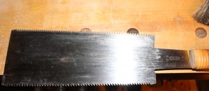
Fast forward 10+ years and my Mother-in-law and Father-in-law went on a trip to visit family in Japan, and were nice enough to ask what I’d like them to pick up for me. As you might imagine, a ton of different tools flooded my mind, but trying to not take advantage of the family, I told them I’d love to have a nice Ryoba saw. The Ryoba is a saw that has rip teeth on one side of the saw-plate and cross-cut teeth on the opposite side. Since there is no stiffener or back on the saw plate, like you would see on a Western back saw or a dozuki, the saw can cut as deep as you need, or that it can reach.

1 Ryoba flat

Since I’ve had my Ryoba well over 20 years, and the saw has seen quite a bit of wood, the rip side of the saw has gradually become somewhat dull. You are probably wondering why I didn’t just sharpen it earlier in it’s life when I first started noticing it was slowing in it’s cutting? As part of the answer, there are basically two generic types of Japanese saws on the market, such as the hand-made saws that are hand-sharpened and set, and the other type that are machine-made with impulse hardened teeth. Since I hadn’t specifically asked my family to get me a high-end saw, I assumed my saw likely had the impulse hardened teeth, where the hardening of the plate makes the steel at the teeth harder than a file, so you can’t re-sharpen it. Another attribute of the impulse hardened teeth is that they will stay sharp longer, which seemed as if it also fit with my saw, since it really was relatively sharp for a long time.

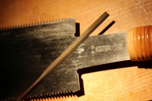
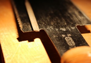
A few days ago, I was cutting some tenons with my Ryoba and it felt like it was just spinning it’s wheels (in a sense), since it was just barely making any progress even after a number of strokes. I knew I didn’t have the feather files that are used to sharpen Japanese saws, as they are a totally different shape than those used to sharpen Western saws, but I remembered that I did have one file that was somewhat similar in shape. My uncle gave me a small bundle of files, that ranged from round, square, triangular, as well as the one that was similar to the feather files. I pulled that file out and was happy to find it fit into the narrow angle that is between each tooth.

2 Ryoba file2 3 Ryoba file xsection 5 Ryoba holder file phone

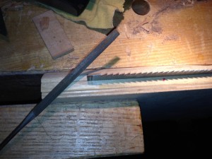
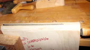
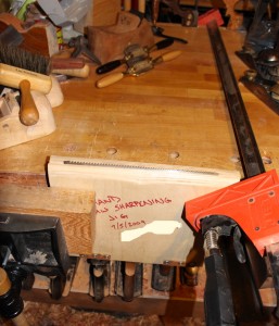
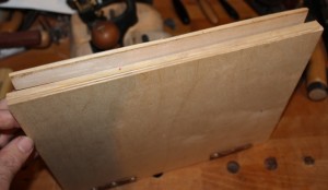
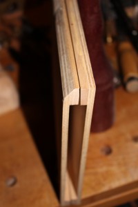
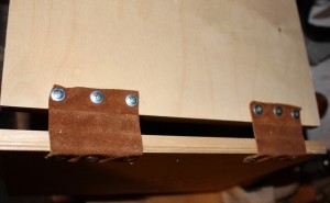
I pulled out a jig (saw holder) that I made about five years ago, that I use to hold my saws when sharpening. The holder is constructed of a couple of pieces of plywood, some hardwood strips, some small pieces of flexible leather used as hinges, and a few screws. When sharpening a saw, I usually put the holder into my dovetailing vise, which applies a good pressure all the way across the holder and onto the saw plate. As I’ve recently rebuilt my dovetailing vise, and it is not 100% complete, I thought I’d show plan “B”. When I put my saw plate into the holder, I position it so it’s teeth are just above the holder’s jaws, enough so the saw’s gullets are accessible without the file making contact with the holder. The closer the gullets are to the holder’s jaws, the better, as this leaves the least amount of tooth out possible, eliminating as much vibration as possible when sharpening. I placed one end of the saw holder into my bench’s face vise and used a long parallel-jaw clamp to hold the jig’s other end, with the other end of the clamp on the other side of my bench. This arrangement allowed me to hold the saw-holder and saw securely, while retaining full access to the saw teeth.

4 Ryoba plate in holder

9 Ryoba jig clamp

6 Holder wide

7 Holder endshot

8 Holder hinge

As with any saw (and sometimes plane irons and chisels), I applied some sharpie to the surfaces of the teeth I planned to try sharpening, as it allows you to verify the critical area at the tooth’s point is contacted by the file. It is also much easier to keep track of which teeth you haven’t yet sharpened, as the marker ink is removed as the file removes the metal from each tooth’s surface.

So now it was time to see what would happen when the file meets the saw. I turned on my overhead light source, grabbed my magni-focuser and file and took a stroke on the first tooth, while subconsciously holding my breath. I really expected the file to feel like it was sliding across the tooth, basically unable to “bite” into the steel and remove material, but it surprisingly felt much like it does when sharpening my other saws. I thought it might just be an odd tooth that didn’t get the “full” treatment of the hardening process, so I moved on to the next couple of teeth. I again took some light file passes on these teeth and they responded exactly the same way, which indicates the steel was not impulse hardened and will accept resharpening. Since the file I have isn’t as large across it’s width as many feather files, it took two strokes to cover the distance from the gullet to tip on one side of the tooth, using one stroke out towards the tip of the tooth and one down towards the gullet. The size of the teeth on the rip side of my Ryoba was almost exactly twice the width of my file, so there wasn’t much  overlap (if any) of the file strokes, so uneven wear in this current sharpening is not a concern. Now that I’ve determined this saw can be re-sharpened, I’ll likely order a couple of feather files, available at Highland Woodworking, for future
sharpenings. While I feel completely comfortable sharpening the rip side of my Ryoba, as well as both rip and cross-cut teeth on Western style saws, the cross-cut side of the Ryoba has teeth with more facets than a high-end diamond (ok, I’m exaggerating a bit), so it would probably be best left to a professional sharpener.

Unlike my Western saws, where the triangular files remove metal from the back of one tooth and the front of the adjacent tooth simultaneously, I had to work each side of every tooth as a separate process. This is due to the fact that my file isn’t made with the same angle between the teeth. This really isn’t that big of a deal, as it just adds a little extra time to the operation. One important detail I want to make sure to mention is how important it is to use consistent pressure and the same number of strokes on each tooth surface. Since my Ryoba had only ever been sharpened at the time it was made, I felt comfortable leaving out a step that very likely would be necessary for any older or second-hand Ryobas you might obtain. The step I’m referencing is jointing the teeth, which is where a flat file is pushed down the teeth along the length of the saw’s plate, with the file perpendicular to the plate of the saw. This, just like sharpening, is best completed with the saw plate held in the same holding jig and vise so the rip teeth all point to the sky. Hold the file so it is parallel with the ground, and lightly push the file from one end of the saw to the other. This will create a very small flat on the tip of all the teeth it touches. After the first pass with the file, check to see how many of the teeth’s tips have a new small flat area. If you see that all of the teeth’s tips have a flat, you are ready to start sharpening. If on the other hand, you have teeth that show no signs of a flat, this indicates those teeth are shorter than those that already have a flat. This uneven height is something that usually occurs over multiple sharpenings, as more pressure is used or more passes are taken on some teeth than on others. Continue to take passes with the jointing file until the tip of all the saw’s teeth have at least a slight flat on them. This is your indication to stop the jointing operation.

When sharpening following jointing, you should take equal passes with the file on each side of each tooth, removing half of each flat from one side of a tooth, and the other half from the opposite side. By working from both sides of a tooth, in an equal manner, it helps to prevent changing the characteristics of the teeth. Make sure to stop the filing process when the flat just disappears. It can seem that additional passes must make the saw that much more sharp, but it will be wasted time, energy and the saw will not last as long.

Another aspect of sharpening that my Ryoba didn’t require was that of setting the teeth. The set is how each alternating tooth is slightly bent to one side and then the next the opposite direction. The amount the tips of the teeth are bent is very minimal, with some saws only adding about .002” of set per side, which helps to create a small amount of room in the kerf so the saw doesn’t bind. It might seem that if a little set is good, then more would be even better, but as more set is added to a saw, it can quickly change from a very easy and controllable saw to one that wanders all over the place and is very difficult to control. As saws are sharpened repeatedly, the saw can start to feel like the kerf is getting more tight, as the tip of the teeth are bent to create the set. As the saw is sharpened, material is removed from the tip, which diminishes a small amount of the set. If the saw feels too tight in it’s kerf, it is likely time to add some set back to the teeth’s tips. Some saws are set with a light strike from a small hammer, while others are set using a tool called…, you guessed it, a Set. It somewhat resembles some of the old label machines, where you’d turn the dial to a letter and squeeze the handle, to impress that letter onto the plastic strip. These set tools are available in both course and fine versions at Highland Woodworking, so make sure you pay attention to the number of points per inch on the saw(s) you intend to set, or at least the range of points as most of these sets are adjustable to a number of different settings.

After I finish the filing on a saw I’ve just sharpened, I like to pull (or push as is appropriate to the saw style) the saw through some scrap wood, like pine or maybe mahogany, to remove any leftover burrs on the teeth. Now the saw is ready to again perform up to it’s full abilities. Go enjoy the freshly sharpened saw and pay attention to how it behaves. When it drifts too far away from this behavior, repeat this process. Each time you sharpen a saw, you’ll get better with your technique and the next one will be even faster.

I hope you enjoyed this article. Please let me know if you have any questions or comments.


Lee Laird has enjoyed woodworking for over 20 years. He is retired from the U.S.P.S. and works for Lie-Nielsen Toolworks as a show staff member, demonstrating tools and training customers. You can email him at lee@lie-nielsen.com or follow him on Twitter at twitter.com/is9582

Mar 052014
 

CLICK HERE to read Part 1 of Lee Laird’s Wooden Square Build.

Now that we’ve created a perfectly fitting half-lap joint, let’s move on.

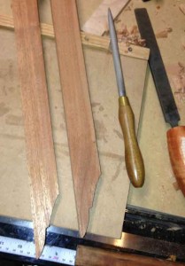
First we’ll address the shaping of each leg, at the opposite end from the half-lap joints. On my design, I measure from the outside edge of each leg, and mark it at 1/2”. Using a marking gauge, start at this point and mark down the leg about 1 1/2”. Using a small square, draw a line from the last mark, approximately ¼” towards the inside edge of the legs. This is laying out the flat between the two curves that are on the end of the legs. From this line drawn across the leg, measure down an additional 1 ½” and make a small pencil mark on the inside corner of the leg. Take your pencil and draw a curve from the outside corner of the end of the leg, to the outside most portion of the line across the board. This curve should bulge towards the inside edge of the board. The second curve is drawn from the pencil mark on the inside corner of the leg, back to the square line across the board, but meet at the portion closer to the inside edge of the board. The second curve’s bulge is towards the outside edge of the board, or the opposite from the first curve.

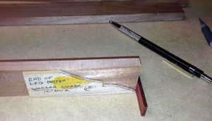
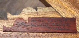
The first cut to make is from the inside edge of the board, along the square line you drew. This makes it easier to cut the curve at the end of the board, and not need to back out after reaching the end of the cut. Next cut the remaining curve from the inside edge of the board. You can make the curved cuts with a band saw, a coping saw or any tool you have that you feel comfortable using. Since I planned to make multiple squares, I made a small wooden template for this double-curved section as well as the upcoming ogee. The ogee template is something I might make, even if I was only making a single square, so all six of the ogees on the square are close to identical.

2015-leg-end-pattern

This is the pattern for the double curve for the end of the legs.

 This is how the curves look on the end of the legs.

This is how the curves look on the end of the legs.

My ogee template on top of the cross member, close to actual ogee. I line up the end with the hook, with the place where the wood steps down, so the template could be longer.

My ogee template on top of the cross member, close to actual ogee. I line up the end with the hook, with the place where the wood steps down, so the template could be longer.

This next portion is to create the ogee on the inside edge of the legs, just before the legs narrow. Measure 1 inch back towards the half-lap joint (and mark it with a pencil) from the step in the leg you created earlier when you removed the 5/8” wide section of wood. (This section is used if you did not create an ogee template.) At this mark, use a square to create a line across the thickness of the board. Using a crosscut saw, cut down approximately ¼” at your line. The ogee begins from this cut and ends at the step. To create this ogee, draw a half-circle up from the bottom of this saw cut to the same surface where the cut began, and back down. The half-circle should have a radius of approximately 3/16”. At the other end of the half-circle, create a smaller half-circle that swings in the opposite direction, or away from the inside edge of the board. The end of this second half-circle should end just short of the step, so the end isn’t overly weak.

To create the ogee shape you’ve drawn, I like to use a chisel and rasps, but you could cut them with a saw if you’d rather. Place the leg into a vise or clamp with which you can restrain the leg while you work to remove material. The section closest to the saw, cut across the board’s thickness, is where I use the chisel to remove the small corner, beginning the start of the ogee, and then follow that cut with a very fine modeller’s rasp. To help expedite the process, I also cut down to almost the very bottom of the second half-circle with my crosscut saw. A fine rat-tailed rasp and a modeller’s rasp are both very useful at removing remaining wood while providing a good amount of control. Sand the ogee surfaces, with fine grits until you are satisfied with the look/feel. Repeat this process on the other leg’s inside the ogee.

Leg with partially cut ogee, held in bench vise, ready to complete.

Leg with partially cut ogee, held in bench vise, ready to complete.

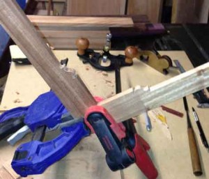
You probably won’t believe it, but it’s finally time to glue the half-lap joint together. Get your glue, a small brush, a couple of clamps, a rag or two, a cup of water (to use when cleaning any excess glue), and the two small slabs you removed when cutting the half-lap joint. I usually lay down some wax paper or some plastic on the surface where I plan to glue so I don’t have a lot of cleanup after I’ve finished. I also like to apply some paste wax to the faces of the wood slabs so I can use them as cauls without them accidentally getting glued to the project. I pour some glue onto a small paper plate and use a tiny brush to apply it to the joint surfaces. This can help provide a nice level of control over the volume of glue in the joint. After the glue is applied, get the pieces together in the correct orientation (make sure the nice pretty ogees are on the inside edges of the legs), and put the slabs on each side of the joint and apply a little clamp pressure. Since this is such a small joint, it doesn’t take much pressure as you’re really just trying to keep the joint solid and prevent the parts from moving around. Give it one last look to make sure nothing has gone crazy, and if it’s good, set it aside to dry.

The two legs glued and clamped.

The two legs glued and clamped.

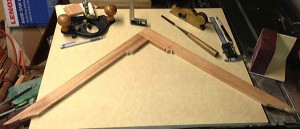
Legs after the glue dried, and out of the clamps.

Legs after the glue dried, and out of the clamps.

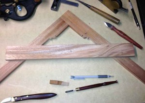
While the legs are clamped together, you can lightly offer the cross member up to them, so you can mark where the inside surfaces of the legs will mate. Once you have those marks, you can proceed to layout and create the ogees on this board (four of them), as well as the narrowing of the center section. If you aren’t in a hurry, you can always do these details later after you’ve cut the angled half-lap joints that mate the three boards together. Waiting isn’t really such a bad idea, as the center section of the cross member does get fairly narrow and with that, it’s strength is reduced. I’d hate to have you snap that board, after spending time creating the ogees and all, while cutting the joints and cleaning them up. I cut the remaining half-lap joints on the few I’ve made before moving on to the ornamentation, but in the end, its up to you. When laying out the ogees on the edge of the cross member that is closest to where the legs join, the saw cut is approximately ¾” in from where this meets the inside edge of the leg board. The overall length of these ogees are the same as those previously created on the legs. The ogees on the lower edge of the cross member are approximately 1” in from the inside edge of the leg boards. At the end of the ogees, make a saw cut across the boards thickness, down approximately 3/16”. The wood between these last cuts will be removed, leaving a lighter feel to the straight line between the ends of the ogees, while also stepped down.

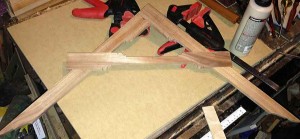
Cross member laid across the legs, to get an idea of correct look.

Cross member laid across the legs, to get an idea of correct look.

After the  leg joint is dry, offer the cross member up, and when the placement looks good, clamp it in place on both legs. On my squares, I placed them so the top of the cross member was approximately 8” down from the end of the leg (the half-lap end). With the cross member clamped in place, scribe around all sides of the mating pieces. Similarly to the earlier handling of the leg’s half-lap, work the joint surfaces to just shy of fully half thickness on adjoining pieces, and then sneak up on the perfect fit. I used my crosscut saw to make multiple cuts (5-7) in each of the remaining joint areas, cutting close to half the way through the board, and then followed that with my chisels to remove the rough waste.

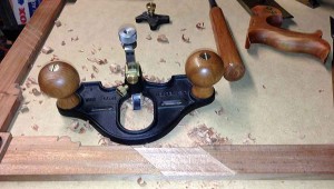
The router plane followed, as it does such a great job of creating a surface parallel with whatever the plane rides on, and if that is an already flat face, the joint surface will also be flat and in the same plane. Leave the cross member at full length until after the square is glued up and dry. Its easy to trim the remaining ends off at that time, and the outside ledges help to hold it together, mainly requiring just a little pressure over the joint. Handle the glueup in the same manner as the leg half-lap and there shouldn’t be any problems.

Saw across the joint before cleanup.

Saw across the joint before cleanup.

Joint cleaned up with the router plane.

Joint cleaned up with the router plane.

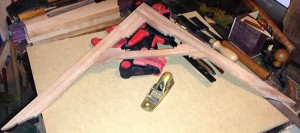
Legs and cross member glued up, with “ears” still attached.

Legs and cross member glued up, with “ears” still attached.

“Ears” trimmed all around. All is complete except for sanding and oiling.

“Ears” trimmed all around. All is complete except for sanding and oiling.

Two completed squares; one with tung oil applied and the other ready for oil.

Two completed squares; one with tung oil applied and the other ready for oil.

After the glue has dried, trim off the excess ends of the cross member, as well as any little excess that protrudes at the leg-to-leg half-lap. Check your square to see that it is truly 90-degrees from one leg’s outside edge to the other. To check this, you can place it inside a known good square, or line up one leg’s outside surface with a known flat surface, like the front of your workbench. Draw a pencil line across the surface using the opposite leg’s outside edge. Flip the square over so the same leg’s outside edge is aligned with the front of the bench, and draw a second line using the outside edge of the same leg. Check to see if the two lines are parallel. If they are, you passed and the square is “Square”!

It’s not the end of the world if this isn’t the case, since you can adjust these to bring them into square. This is one of the nice things about making these from wood. If the angle between the outside edges of the legs is reading less than 90-degrees, a little material should be removed down towards the leg’s joint area on both sides. If the angle is more than 90-degrees, some material from the outside edge near the toe section should be removed. Of course, when removing any of this wood, you’d need to feather the amount removed into the full length of the same edge.

Now you can sand and finish your square in any manner you see fit. I sanded to 320 grit and followed that with some Tung Oil, which really brought the wood to life. I always mark my pieces with my burning tool (I still need to design and order one of the marking tools, so my mark is more consistent) and include at minimum the year, but sometimes the month and year. I think its cool for your family, friends, and customers to look back and recall when a piece was made.

I hope you’ve enjoyed the article and will make at least one wooden square. There are a range of techniques you’ll use during this build and like most things, the more you do, the more proficient you become. Please let me know if you have any question or comments.


Lee Laird has enjoyed woodworking for over 20 years. He is retired  from the U.S.P.S. and works for Lie-Nielsen Toolworks as a show staff member, demonstrating tools and training customers. You can email him at lee@lie-nielsen.com or follow him on Twitter at twitter.com/is9582

Mar 042014
 

Every once in a while I’ll see a tool/project that calls to me. You know, one of those “whatchamacallits” that real people probably don’t really need, but looks so cool? As you might imagine, the majority of THOSE projects never see the light of day in my shop. Luckily, there are also some other projects that REALLY, REALLY, call to me, and just happen to be both cool and useful. This article is about one of these latter types of projects.

Christopher Schwarz, who is a friend of mine, and someone almost everyone in the woodworking community knows, teaches how to make a really cool wooden square. After seeing his, I just had to give it a try. While Chris’ pattern is straight from an old original square (which I believe was inadvertently destroyed when in transit by a package handling company), I created my pattern simply by eye-balling the square Chris showed on Roy Underhill’s “The Woodwright’s Shop”, and extrapolating what dimensions looked right to me.
2108-Square-oil-bench

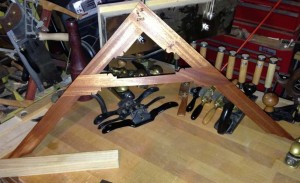
A quick photo of my square in front of some of my tools.

After seeing that the square is made from only three pieces of wood, I figured I’d go spend an hour or two in the shop and have a square. Well, I’d have to say my time estimation and management skills must have been very lacking that week. Ok, it didn’t actually take me a week to make the first one, but the time was certainly adding up. And this was with me already having the necessary wood milled up to 1/2” thick, which I’d originally planned to use on a dovetailed box project. The box will just have to wait!

To start out, I cut two legs 22” long x 2” wide x 1/2” thick, and one cross-member 20” long x 2” wide x 1/2 thick. Before cutting any of the decorative shaping, I hand planed each board, making sure they were both square and flat. Much of the next work is focused on the two “leg” boards, since its only after they are glued into a solid unit, that you can identify exactly where the cross-member will intersect the legs. If you try marking the locations to evacuate for the cross-member, without first gluing the legs, I’d suggest your chances of success would be diminished.

Before marking either of the two “leg” boards, you’ll want to examine them for any imperfections and read through the meat of the project, as it’s possible you just might be able to plan for any problem areas to fall in the region that will be removed as waste. Since the square’s design uses a half-lap joint where the two legs intersect, there is a fair amount of wood removed, which you can also view as an opportunity. If either of your leg boards have any tear-out or other quality type issues in the first 2” of the board, you can orient them so the problem section will reside on the slab of wood you remove when forming the joint. But, before finalizing any cuts or using any cutting tool to mark, I find it’s a good idea to lightly sketch out the complete layout, so you can weigh your options on which areas of wood might create the least amount of extra work. At the minimum, this will at least give you the chance to choose the best orientation for each board. It may just be that the half-lap joint area is of less concern than another area. If you’re really into planning, or end up being lucky, you may also find a similar benefit when positioning the cross-member, but there are only a few ways to orient three boards. You’d may as well take every advantage to eliminate blemishes on your project, especially when it only takes a few moments to flip the boards around, testing for the best orientation.

Now that you’ve looked everything over, its time to get on with the design, which obviously includes the areas you’ll cut away as well as the design features on the legs. To start, I measure down approximately 6 inches from the end of the board that will contain the half-lap joint and place a pencil mark across the board, on what will be the inside edge. This top section of the board will stay full width and includes both the half-lap joint as well as some figurative work before the leg narrows. Measure in 5/8” from the location you just marked, and using a square, run a line to the other end of your leg board away from the half-lap end. This line should be parallel to the edge of your board.

Repeat this process on your other leg board, as the design is identical on both legs.
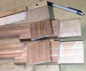
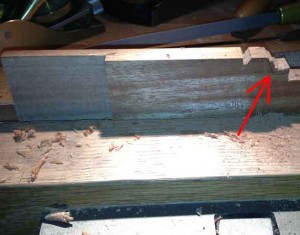
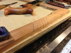
It is approximately 6 inches from the end to the notch just left of the off-cuts, which is from the 5/8” cut. You can also see the large X on the slabs which identified the waste, and the saw marks still on the lap joints before using the router plane.

It is approximately 6 inches from the end to the notch just left of the off-cuts, which is from the 5/8” cut. You can also see the large X on the slabs which identified the waste, and the saw marks still on the lap joints before using the router plane.

Cut the short 5/8” deep cut from the inside edge of the board first, followed by the long cut from the end farthest away from the intended half-lap joints. Making the short cut first is much easier than trying to back out of a long cut. Use whatever saw you have available that can reach this far into the wood, like a band saw, a bow saw or a panel saw. This cut will generate a 5/8” wide piece of wood that is approximately 16” long. (anyone up for making a kite?)

The next step is to mark out for the half-lap joint for the legs. Set your marking gauge directly from the width of the first board, and add a hairs width extra. With the gauge head riding against the end of the second board, lightly mark across the width of the board, which transfers the first board’s dimensions. Make a couple of additional passes, applying a little more pressure on the marking gauge on each pass.Before moving on, take your pencil and make an “X” on the leg above the mark you just made. This will remind you that this is the side from which the wood is removed, which can help prevent errors. Repeat the process for the other board, but remember to set the gauge from the opposite board’s width, just in case they aren’t exactly the same size. Next you’ll mark the center line of the board’s thickness on the end and the sides of the board, down to the line you’ve just marked across one face. I dial in my marking gauge directly from the thickness of the board, by lightly touching the cutting gauge to the board while the head is against one side, and then doing the same from the other side. When the gauge hits the same spot from both sides, you’re there. I still like to add an extra hair’s width, so there is a little extra material to dial in the perfect joint, which I’ll talk about later.

While holding the gauge’s head against the side of your leg that will remain (the side without the big “X”), mark across the end and down both sides, to your line across the leg. If you accidentally reverse the gauge, so the head is against the side you plan to remove, you’ll end up with a joint that’s isn’t as thick as the original leg.
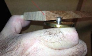
Showing gauge out to depth and red arrow points to centering mark from each side.

Showing gauge out to depth and red arrow points to centering mark from each side.

Now that your leg’s half-lap joint is marked, it’s time to remove the excess wood. The first cut is at your mark across the leg, but I like to give myself the best chance to succeed. Instead of just grabbing my crosscut saw and going for it, I use a razor sharp chisel to carefully pare away a small angled piece of wood, across the width of the board. I do this on the waste side of the marking gauge’s line, to create a small V-shaped path, which helps keep the saw from wandering during the initial strokes. Now use a crosscut saw to carefully saw down, until you just about kiss your gauge lines on both sides, which is very close to half way through the board.

The next operation is to saw down length-wise following the marks made on the sides and end. Since this cut is with the grain, use a fine-toothed rip saw, of which I prefer to use a thin-bladed dovetail saw. Place the first leg board into a vise with it tilted so the top end of the board is just slightly away from you.

This is another good place to apply a helpful tip, which is to remove a small wedge shaped piece of wood at the corner of the board closest to you. With a sharp chisel, place it so the flat back lines up with the mark you’ve made across the end of the board, push the chisel into the wood so it is contacting the corner. Turn the chisel around so it’s back is away from the line and at about a 45-degree angle, push in again, so the two cuts meet. This should pop out a small wedge of wood that will act similar to the cross-cut version earlier, but the starting “V” is not all the way across the end. Start with the toe of the saw raised up slightly, so it is not making contact across the full width of the board’s end. With light, short strokes, let it gradually drop, as you look to make sure you follow your mark. When the saw is down to the point where it is touching across the full width, focus on following the line on the side of the board closest to you, cutting down to the baseline. This ends up being an almost purely diagonal cut, since you are only trying to advance the saw plate on the side you can observe.

Next, remove the board from the vise and flip it around so you have the other side of the board facing you. Again tilt the board so the end is slightly leaning away from you, and again make the same diagonal type cut down to the baseline on this side. Next, it is just a matter of placing the saw into the already created kerf, and while holding the saw so the teeth are parallel to the baseline, cut down through the remaining triangle-shaped section of wood. Be very careful at this stage, especially when you’re getting close, that you don’t cut down below the baseline, which can happen if the saw tilts forward. Since you can’t see the opposite side of the cut, without moving your head around, this is the most common place to over-cut. This will leave you with your basic half-lap shaped end on your leg board.

Repeat these steps on the other leg board. When I make these cuts, I saw so I am cutting really close to the line, but making sure I don’t dip down into it by accident. You can base how close you cut to your lines, on your comfort level with a saw, but remember I’ll share additional techniques that will help create a perfect fit.

Next, we’ll get out the router plane, which is a perfect companion for the upcoming tweaks to the wide mating surfaces of the lap joint. Clamp a leg board so it is sitting with the half-lap portion facing upwards from the bench. Place the other leg on one side of the first leg, and the cross member on the other side of it, so the router plane can ride on two rails of the same thickness. With the router plane on the two flanking boards, lower its iron down until it just grazes the highest point on the lap joint. (It’s also a good idea to check to make sure the iron isn’t below the line that was earlier marked down the side of the leg board, as that could be close to removing too much material.) Move the router plane back and forth so it’s iron travels over all areas of the half-lap, while riding on the two side boards. Gradually advance the iron so a very light shaving is taken from all areas of the joint. Before removing any material below the lines you marked earlier, do the same process to the other leg’s half-lap. Test the two pieces together, to see if the joint is still thicker than either leg, which would indicate additional material is still remaining. Continue to remove very light shavings equally from each surface until the full joint is exactly the same thickness, when compared to the original thickness of either leg.

The last half-lap related assessment for this joint is of the earlier-cut shoulders, across the legs. Check to see if the shoulder is both square across the board and square to the inside faces. If either of these are out of square, they will prevent the two boards from mating properly, with gaps and/or legs that are not 90-degrees from one another. If there are obvious gross adjustments needed, you can use a sharp chisel (or a rasp) to get it close to the proper alignment, but I’d hesitate to use that tool for the final adjustment. The shoulder plane is my tool of choice for this work, as its wide sides register against the earlier flattened faces, creating perfect 90-degree shoulders. Set the shoulder plane for a very fine shaving, and make sure to keep the side of the plane against the reference surface. Also, check to see if there is any grain runout in either direction, as the shoulder plane works equally well on either of its sides. It only requires you to set the iron so its outside edge is in line with the plane’s body. If you cut the earlier shoulders just proud of your marking lines, you can easily bring the excess material down to the line, knowing you’ve reached the stopping point. If you didn’t leave your line, you could always re-mark down about 1/64” (remember to do this on both legs, and reference from the joint end of the board, just so everything stays symmetrical), so you don’t have to guess where to stop. This isn’t super critical for this tool, as long as the shoulder is square in both discussed dimensions, no one will notice if you don’t tell.

Now, before you get excited and decide to glue your perfectly fitting half-lap joint together, remember we still have some more work to do and it is much easier to accomplish while the legs are still separate from each other. We’ll get to this in Part 2, so stay tuned with our Wooden Square Build!

CLICK HERE to go to Part 2 of the Wooden Square Build.


Lee Laird has enjoyed woodworking for over 20 years. He is retired from the U.S.P.S. and works for Lie-Nielsen Toolworks as a show staff member, demonstrating tools and training customers. You can email him at lee@lie-nielsen.com or follow him on Twitter at twitter.com/is9582
Mar 032014
 

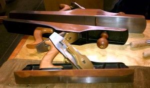
This month I’ll talk about both sizes of the Lie-Nielsen Froes. Now, some tools are extremely commonplace, as in it seems like many of us came out of the womb knowing what they are, like a hammer, a chisel, or a screwdriver. On the other side of the coin are tools that seem to have had a bit more limited exposure, like a froe. When I was first getting interested in woodworking (24 years +/-), I happened across a book that was a compilation of old woodworking articles, and in one article, they mentioned using a froe. Since I’d never seen a froe personally, at that point in time, I found it both unique and interesting.  After reading the article (wish I could recall the author), occasionally I’d see an old froe at a garage sale, an estate sale, or even at an antique store. Many of the old froes I’d see were in such bad repair they were really no longer worthy of work, even though they ran the quality spectrum, from nicely crafted blacksmith units to those cobbled together by a user snatching an old leaf spring from a truck, and bolting on a piece of wood for a handle.

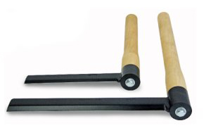
Enter the Lie-Nielsen Froe, designed in cooperation with Drew Langsner. Drew is an expert with regard to riving or splitting green wood with decades of experience, translating this knowledge into newly designed familiar tools. He redesigned the traditional froe with several key improvements. The large version of his froe has a blade 3/8” thick x 1 1/2” wide x 12” long, and a 17 1/2” long handle of hard maple. The smaller version has a blade 1/4” thick x 1 1/4” wide x 8” long, and it’s handle (also hard maple) is 13 1/4” long. The large froe’s longer handle (think levering action) and thicker blade (more rigid to adequately apply the extra levering forces) make it the obvious choice for working larger pieces of wood, but it can also easily finesse smaller pieces. If you will never even think about splitting a larger piece of wood, and you prefer a nimble and lighter tool, the smaller froe is for you. Those of you familiar with froes will immediately notice a few unique aspects of these Lie-Nielsen froes, such as the manner in which the attachment point is created and the handle attached, as well as the thickness of the blade. Rather than taking a single piece of metal for the blade and creating an eye for the handle by wrapping one end of the metal back around to itself, the blade is welded to a cylindrical ferule. This ferule is sturdy, having no weak areas like many of the older froes. The old froes also usually had a tapered eye, so the blade couldn’t accidentally slide off of the wooden handle in the working direction. Where the old style was basically a wedge/friction fit, the new Lie-Nielsen froe’s ferule is held onto the end of the handle with a stepped washer and a large lag screw. The working edge of the blade that contacts the project wood is beveled at 30 degrees. This beveling facilitates easier entry into the wood, which can decrease the amount of force required from your mallet or maul, potentially increasing the life expectancy of that accessory, too. The 30-degree bevel is suitable for use in either hard or soft woods.

For those of you who have never before tried a froe, or may not have ever even seen one, let me describe some basics. A froe is an “L” shaped tool, with a straight piece of metal connected at a 90-degree angle to a wooden handle. The froe is used primarily on green wood (wood that hasn’t yet dried). The froe’s metal blade is placed on the end-grain of the wood you wish to split, and a large wooden mallet is swung down onto the back of the blade, driving the blade into the wood. Depending on the wood (or your strength this morning), it may take a couple of good heavy whacks to move the blade deep enough to either initiate the splitting action, or position the froe so you can force the wood to split. Some wood will just easily give up, and split as though you were the master of the universe. Others will mock you, and do everything but call you names, while refusing to split. After the froe is down into the end-grain about a full blade’s depth, you can either pull the handle towards yourself, or push it away to utilize what might best be called the levering action. This is where the thin blade of the froe is rotated in the wood, so the opening that started about 1/4”-3/8” (the blade’s thickness) or so, is forced open gradually. As the blade rotates, not only does the opening become wider, but the split also runs further down the piece. Now move the blade further down, into the new area of the split, and rotate the blade again. Depending on different factors, you may need to place wedges in the gap behind the froe to help keep the initial split open while working down the wood. This process is repeated until the split is open the full length of the wood, and you end up with two separate pieces. Since the wood from this process follows the grain, you end up with blanks/boards retaining all of the wood’s original strength. This grain continuity is exceptionally useful and especially sought after for a multitude of uses, including green furniture making and more.

I hope you enjoyed the article and please let me know if you have any questions or comments.

Click to take a closer look at the Lie-Nielsen Froes.

Click to see Highland Woodworking’s entire selection of Lie-Nielsen hand tools.


Lee Laird has enjoyed woodworking for over 20 years. He is retired from the U.S.P.S. and works for Lie-Nielsen Toolworks as a show staff member, demonstrating tools and training customers. You can email him at lee@lie-nielsen.com or follow him on Twitter at twitter.com/is9582

Jan 072014
 

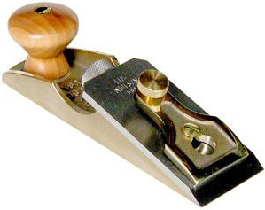
smallchiselplaneThe Lie-Nielsen Small Chisel Plane (97 ½) is something that never fails to catch attention. This is likely in some part due to a unique design with the cutting edge of the iron at the very front of the plane. That’s right, there is absolutely no toe section out in front of the iron, as is common for most types of planes. While this might seem like a deficiency, and could cause definite problems for a multitude of operations on most planes, the function of the 97 ½ is anything but ordinary.

The length of the plane is 6 ½”, width is 1 ¾” , and the A2 tool steel iron is a hefty 3/16” thick by 1 ¾” wide. The iron is bedded at 12-degrees, so it falls into the category of low-angled planes. The cap and body of the 97 ½ are Bronze, increasing the plane’s heft, as well as eliminating the issue of rust (bronze can still oxidize, so light oil protection is useful) on the plane. Add on the rich hues from the Cherry knob and it is one beautiful plane. The plane weighs in at 2.35 lbs, which feels as if it’s dialed in perfectly; not too heavy nor too light.

The iron comes from the Toolworks with a 25-degree bevel and I hone it  with a 10-degree micro-bevel, raising the overall angle on the iron to 35-degrees. The honing process I use is exactly the same as for almost every other plane iron, and since I’ve covered this in previous articles which are on this blog, I won’t repeat it here. If you would rather watch a video on sharpening, check out Lie-Nielsen’s Youtube channel for a great video.

After the iron is honed and on the plane’s body, rotate the cap’s screw until you feel resistance, and then add ½ turn to snug it up. To set the plane’s iron to the proper cutting depth, back off on the cap screw ¼ turn, and while moving the plane forward slowly across a flat piece of wood, rotate the blade adjuster clockwise slowly until the blade just starts to grab the wood. If the iron is hitting on only one corner, gently tap the blade until it is square to the plane body. While applying a slight forward pressure on the plane, start rotating the blade adjuster counter-clockwise slowly, just until the plane moves forward without the iron grabbing the wood. Now re-tighten the cap the ¼ turn removed earlier, and then take up the backlash of the blade adjuster until you just feel tension. The plane is now set to remove material flush with the wood on which it is riding. Remember, since this plane has no toe section in front of the iron, you don’t want to set it so the iron is below the plane’s sole, like is normal for other planes.

The design of the 97 ½ essentially creates a paring chisel with superior depth control, and no handle that hangs down to limit it’s reach. In this vein, it is very useful when working to clean up a dried glue line between boards or panels, resulting in a level surface. Similarly, the 97 ½ can easily trim protruding thin wood banding, dowels, screw plugs, through tenons, proud dovetails, …ending with each type flush to the surface.

Rabbets are occasionally a bit rough  straight from the machine or plane, and with this plane you can quickly make them perfect.

Another technique in this plane’s wheelhouse is cleaning up the surface of a board, up against a mating board. For example, like cleaning up the interior horizontal surface of a box, where it intersects with the sides of the box. This is assuming the corners of the box are 90-degrees. Remember, this plane, like most paring chisels, works most effectively as well as leaves the best surface, when used while moving the cutter in a slight arc. This shearing cut can greatly reduce the chance of some operations to cause some blowout.

I hope you’ll give this plane a try, as I believe you’ll find yourself reaching for it on a regular basis, once its in your toolbox. I’m sure you will likely come up with even more uses for this plane in your work, as I just shared some obvious uses.

I hope you enjoyed the article and please let me know if you have any questions or comments.

You can find out more information and purchase the Lie-Nielsen Small Chisel Plane from Highland Woodworking HERE.


Lee Laird has enjoyed woodworking for over 20 years. He is retired from the U.S.P.S. You can email him at lee@lie-nielsen.com or follow him on Twitter at twitter.com/is9582

Dec 312013
 

resolutions2012As the New Year quickly approaches (i.e. tomorrow), a few of our blog contributors have come up with their 2014 New Years Resolutions with regards to their woodworking (and some personal ones as well). 

First up, we’ve got Lee Laird:

While I’m sure most of you don’t know, I had major back surgery in March, 2012. Luckily I’m making decent progress, even though I’m not 100% yet. As one personal gloat, I have to tell that I did finally complete my Les Paul guitar and even sprayed a decent surface, both were #1 and #2 on my list for last year!

1.      I’m planning to build a hanging tool cabinet, so I can both be more efficient in having my most-used tools close at hand, and also getting my hand planes and other tools away from some dust. I plan to build this before the Lie-Nielsen Open House in July.

2.      I plan to build an upgraded workbench. I’m finding the short length of the current bench is very limiting when trying to plane longer pieces, such as back legs for chairs, or even a potential neck-through Bass guitar.

3.      I want to test my hands at making a chair, as it is one of the core techniques I’ve yet to tackle. I don’t have a set plan, as of yet, but
intend to see what I can do.

4.      This one is just barely on the fringe of woodworking. I will continue my physical training, to strength my body and to primarily regain my old walking gait. I’m finally back to the point where I am spending multi-hours in my shop at a time, hand-planing, sharpening, building…you get the idea. With the continued treadmill and BowFlex work, it won’t be long until people won’t be able to tell I even had surgery. Prior to my back surgery, I loved getting outside and playing golf. I am continuing to swing the clubs, as this movement assists in the progress of my balance, in conjuction with the aforementioned exercises. I am to the point where I believe I can try playing a round (or at least 9 holes, if the body isn’t quite up to it yet), so I have to just keep pushing and testing the body! I’ll continue this resolution point until I am healed 100%!

5.      I will continue to strive for progress in my writings (Blog articles, both Highland and personal), and hopefully provide valuable information and entertainment.

Feel free to contribute your own Woodworking New Year’s Resolutions under “Comments” below.


Lee Laird has enjoyed woodworking for over 20 years. He is retired from the U.S.P.S. You can email him at lee@lie-nielsen.com or follow him on Twitter at twitter.com/is9582